Compaq Presario B1200 Compaq Presario B1200 Notebook PC - Maintenance and Serv - Page 64
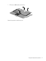
Remove the display bezel, bezel until the bezel disengages from the display enclosure.
 |
View all Compaq Presario B1200 manuals
Add to My Manuals
Save this manual to your list of manuals |
Page 64 highlights
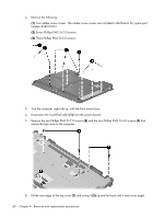
10. If it is necessary to replace the display bezel or the display assembly internal components, remove the six rubber screw covers (1) and the six Torx T8M2.5×6.0 screws (2) that secure the display bezel to the display enclosure. NOTE: See Camera module on page 38 for camera module removal information. 11. Flex the inside edges of the left and right sides (1) and the top and bottom sides (2) of the display bezel until the bezel disengages from the display enclosure. 12. Remove the display bezel (3). The display bezel is available using spare part number 454399-001. 13. If it is necessary to replace the display inverter, release the inverter (1) as far as the display panel cable and backlight cable allow. 56 Chapter 4 Removal and replacement procedures
-
 1
1 -
2
-
3
-
4
-
5
-
6
-
7
-
8
-
9
-
10
-
11
-
12
-
13
-
14
-
15
-
16
-
17
-
18
-
19
-
20
-
21
-
22
-
23
-
24
-
25
-
26
-
27
-
28
-
29
-
30
-
31
-
32
-
33
-
34
-
35
-
36
-
37
-
38
-
39
-
40
-
41
-
42
-
43
-
44
-
45
-
46
-
47
-
48
-
49
-
50
-
51
-
52
-
53
-
54
-
55
-
56
-
57
-
58
-
 59
59 -
 60
60 -
 61
61 -
 62
62 -
 63
63 -
 64
64 -
 65
65 -
 66
66 -
 67
67 -
 68
68 -
 69
69 -
70
-
71
-
72
-
73
-
74
-
75
-
76
-
77
-
78
-
79
-
80
-
81
-
82
-
83
-
84
-
85
-
86
-
87
-
88
-
89
-
90
-
91
-
92
-
93
-
94
-
95
-
96
-
97
-
98
-
99
-
100
-
101
-
102
-
103
-
104
-
105
-
106
-
107
-
108
-
109
-
110
-
111
-
112
-
113
-
114
-
115
-
116
-
117
-
118
-
119
-
120
-
121
-
122
-
123
-
124
-
125
-
126
-
127
-
128
-
129
-
130
-
131
-
132
-
133
-
134
-
135
-
136
-
137
-
138
-
139
-
140
-
141
-
142
-
143
-
144
-
145
-
146
 |
 |
