Compaq Presario B1200 Compaq Presario B1200 Notebook PC - Maintenance and Serv - Page 68
Seven Phillips PM2.5×7.0 screws.
 |
View all Compaq Presario B1200 manuals
Add to My Manuals
Save this manual to your list of manuals |
Page 68 highlights
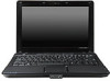
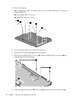
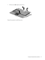
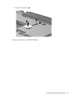
2. Remove the following: (1) Two rubber screw covers. The rubber screw covers are included in the Plastics Kit, spare part number 454010-001. (2) Seven Phillips PM2.5×7.0 screws. (3) Three Phillips PM2.0×3.0 screws. 3. Turn the computer right-side up, with the front toward you. 4. Disconnect the TouchPad cable (1) from the system board. 5. Remove the two Phillips PM2.5×7.0 screws (2) and the two Phillips PM2.5×4.0 screws (3) that secure the top cover to the computer. 6. Lift the rear edge of the top cover (1) and swing it (2) up and forward until it rests at an angle. 60 Chapter 4 Removal and replacement procedures
-
 1
1 -
2
-
3
-
4
-
5
-
6
-
7
-
8
-
9
-
10
-
11
-
12
-
13
-
14
-
15
-
16
-
17
-
18
-
19
-
20
-
21
-
22
-
23
-
24
-
25
-
26
-
27
-
28
-
29
-
30
-
31
-
32
-
33
-
34
-
35
-
36
-
37
-
38
-
39
-
40
-
41
-
42
-
43
-
44
-
45
-
46
-
47
-
48
-
49
-
50
-
51
-
52
-
53
-
54
-
55
-
56
-
57
-
58
-
59
-
60
-
61
-
62
-
 63
63 -
 64
64 -
 65
65 -
 66
66 -
 67
67 -
 68
68 -
 69
69 -
 70
70 -
 71
71 -
 72
72 -
 73
73 -
74
-
75
-
76
-
77
-
78
-
79
-
80
-
81
-
82
-
83
-
84
-
85
-
86
-
87
-
88
-
89
-
90
-
91
-
92
-
93
-
94
-
95
-
96
-
97
-
98
-
99
-
100
-
101
-
102
-
103
-
104
-
105
-
106
-
107
-
108
-
109
-
110
-
111
-
112
-
113
-
114
-
115
-
116
-
117
-
118
-
119
-
120
-
121
-
122
-
123
-
124
-
125
-
126
-
127
-
128
-
129
-
130
-
131
-
132
-
133
-
134
-
135
-
136
-
137
-
138
-
139
-
140
-
141
-
142
-
143
-
144
-
145
-
146
 |
 |

2
.
Remove the following:
(1)
Two rubber screw covers. The rubber screw covers are included in the Plastics Kit, spare part
number 454010-001.
(2)
Seven Phillips PM2.5×7.0 screws.
(3)
Three Phillips PM2.0×3.0 screws.
3
.
Turn the computer right-side up, with the front toward you.
4
.
Disconnect the TouchPad cable
(1)
from the system board.
5
.
Remove the two Phillips PM2.5×7.0 screws
(2)
and the two Phillips PM2.5×4.0 screws
(3)
that
secure the top cover to the computer.
6
.
Lift the rear edge of the top cover
(1)
and swing it
(2)
up and forward until it rests at an angle.
60
Chapter
4
Removal and replacement procedures