Compaq Presario CQ42-100 Compaq Presario CQ42 Notebook PC and HP G42 Notebook - Page 84
System board, Disconnect all external devices connected to the computer.
 |
View all Compaq Presario CQ42-100 manuals
Add to My Manuals
Save this manual to your list of manuals |
Page 84 highlights
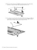
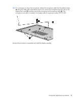
System board Description Spare part number System board for use in models with discrete graphics subsystem 595181-001 System board for use in models with Unified Memory Architecture (UMA) graphics subsystem 595182-001 System board for use in models with discrete graphics subsystem and HDMI card reader 595183-001 System board for use in models with UMA graphics subsystem and HDMI card reader 595184-001 System board for use in models with discrete graphics subsystem and Intel® HM55 chipset 608823-001 System board for use in models with discrete graphics subsystem, Intel® HM55 chipset, and HDMI 608824-001 card reader System board for use in models with UMA graphics subsystem memory, Intel® GL40 chipset, and HDMI card reader 605140-001 When replacing the system board, be sure that the following components are removed from the defective system board and installed on the replacement system board: ● RTC battery (see RTC battery on page 81) ● Memory modules (see Memory module on page 50) ● WLAN module (see WLAN module on page 47) ● Modem module (see Modem module on page 61) Before removing the system board, follow these steps: 1. Shut down the computer. If you are unsure whether the computer is off or in Hibernation, turn the computer on, and then shut it down through the operating system. 2. Disconnect all external devices connected to the computer. 3. Disconnect the power from the computer by first unplugging the power cord from the AC outlet and then unplugging the AC adapter from the computer. 4. Remove the battery (see Battery on page 41). 5. Remove the following components: a. Hard drive (see Hard drive on page 42) b. WLAN (see WLAN module on page 47) c. Optical drive (see Optical drive on page 45) d. Keyboard (see Keyboard on page 52) e. Top cover (see Top cover on page 54) f. Speaker assembly (see Speaker assembly on page 57) 76 Chapter 4 Removal and replacement procedures
-
 1
1 -
2
-
3
-
4
-
5
-
6
-
7
-
8
-
9
-
10
-
11
-
12
-
13
-
14
-
15
-
16
-
17
-
18
-
19
-
20
-
21
-
22
-
23
-
24
-
25
-
26
-
27
-
28
-
29
-
30
-
31
-
32
-
33
-
34
-
35
-
36
-
37
-
38
-
39
-
40
-
41
-
42
-
43
-
44
-
45
-
46
-
47
-
48
-
49
-
50
-
51
-
52
-
53
-
54
-
55
-
56
-
57
-
58
-
59
-
60
-
61
-
62
-
63
-
64
-
65
-
66
-
67
-
68
-
69
-
70
-
71
-
72
-
73
-
74
-
75
-
76
-
77
-
78
-
 79
79 -
 80
80 -
 81
81 -
 82
82 -
 83
83 -
 84
84 -
 85
85 -
 86
86 -
 87
87 -
 88
88 -
 89
89 -
90
-
91
-
92
-
93
-
94
-
95
-
96
-
97
-
98
-
99
-
100
-
101
-
102
-
103
-
104
-
105
-
106
-
107
-
108
-
109
-
110
-
111
-
112
-
113
-
114
-
115
-
116
-
117
-
118
-
119
-
120
-
121
-
122
-
123
-
124
-
125
-
126
-
127
-
128
-
129
-
130
-
131
-
132
-
133
-
134
-
135
-
136
-
137
-
138
 |
 |
