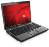
Compaq Presario V6500 Compaq Presario V6500, V6600, and V6700 Notebook PCs - M - Page 83
Fan/heat sink assembly
 |
View all Compaq Presario V6500 manuals
Add to My Manuals
Save this manual to your list of manuals |
Page 83 highlights
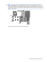
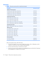
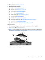
3. Remove the audio board (3) by lifting it straight up. Reverse this procedure to install the audio board. Fan/heat sink assembly Description Spare part number Fan/heat sink assembly for use in computer models with Intel processors (includes thermal material) 446522-001 Fan/heat sink assembly for use in computer models with AMD processors (includes thermal material) 449961-001 NOTE: When replacing the fan/heat sink assembly, be sure that the power button board is removed from the defective fan/heat sink assembly and installed on the replacement fan/heat sink assembly. See Power button board on page 56 for power button board removal information. NOTE: To properly ventilate the computer, allow at least a 7.6-cm (3-inch) clearance on the right side and rear panel of the computer. The computer uses an electric fan for ventilation. The fan is controlled by a temperature sensor and is designed to turn on automatically when high temperature conditions exist. These conditions are affected by high external temperatures, system power consumption, power management/battery conservation configurations, battery fast charging, and software applications. Exhaust air is displaced through the ventilation grill located on the left side of the computer. Before removing the fan/heat sink assembly, follow these steps: 1. Shut down the computer. If you are unsure whether the computer is off or in Hibernation, turn the computer on, and then shut it down through the operating system. 2. Disconnect all external devices connected to the computer. 3. Disconnect the power from the computer by first unplugging the power cord from the AC outlet and then unplugging the AC adapter from the computer. Component replacement procedures 75
-
 1
1 -
2
-
3
-
4
-
5
-
6
-
7
-
8
-
9
-
10
-
11
-
12
-
13
-
14
-
15
-
16
-
17
-
18
-
19
-
20
-
21
-
22
-
23
-
24
-
25
-
26
-
27
-
28
-
29
-
30
-
31
-
32
-
33
-
34
-
35
-
36
-
37
-
38
-
39
-
40
-
41
-
42
-
43
-
44
-
45
-
46
-
47
-
48
-
49
-
50
-
51
-
52
-
53
-
54
-
55
-
56
-
57
-
58
-
59
-
60
-
61
-
62
-
63
-
64
-
65
-
66
-
67
-
68
-
69
-
70
-
71
-
72
-
73
-
74
-
75
-
76
-
77
-
 78
78 -
 79
79 -
 80
80 -
 81
81 -
 82
82 -
 83
83 -
 84
84 -
 85
85 -
 86
86 -
 87
87 -
 88
88 -
89
-
90
-
91
-
92
-
93
-
94
-
95
-
96
-
97
-
98
-
99
-
100
-
101
-
102
-
103
-
104
-
105
-
106
-
107
-
108
-
109
-
110
-
111
-
112
-
113
-
114
-
115
-
116
-
117
-
118
-
119
-
120
-
121
-
122
-
123
-
124
-
125
-
126
-
127
-
128
-
129
-
130
-
131
-
132
-
133
-
134
-
135
-
136
-
137
-
138
-
139
-
140
-
141
-
142
-
143
-
144
-
145
-
146
-
147
-
148
 |
 |
