Compaq Presario V6500 Compaq Presario V6500, V6600, and V6700 Notebook PCs - M - Page 84
Disconnect the fan cable, Removal and replacement procedures
 |
View all Compaq Presario V6500 manuals
Add to My Manuals
Save this manual to your list of manuals |
Page 84 highlights
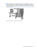
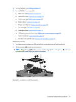
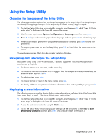
4. Remove the battery (see Battery on page 41). 5. Remove the following components: a. Hard drive (see Hard drive on page 42) b. Optical drive (see Optical drive on page 50) c. Switch cover (see Switch cover on page 52) d. Keyboard (see Keyboard on page 54) e. Display assembly (see Display assembly on page 58) f. Top cover (see Top cover on page 64) g. Audio board (see Audio board on page 74) h. USB/power connector board (see USB/power connector board on page 70) i. System board (see System board on page 71) Remove the fan/heat sink assembly: 1. Turn the system board upside down, with the expansion port 3 and external monitor port toward you. 2. Disconnect the fan cable (1) from the system board. 3. Loosen the three Phillips PM2.5×5.0 captive screws (2) and the Phillips PM2.5×4.0 captive screw (3) that secure the fan/heat sink assembly to the system board. 4. Remove the fan/heat sink assembly (4). NOTE: Due to the adhesive quality of the thermal material located between the fan/heat sink assembly and system board components, it may be necessary to move the fan/heat sink assembly from side to side to detach the assembly. 76 Chapter 4 Removal and replacement procedures
-
 1
1 -
2
-
3
-
4
-
5
-
6
-
7
-
8
-
9
-
10
-
11
-
12
-
13
-
14
-
15
-
16
-
17
-
18
-
19
-
20
-
21
-
22
-
23
-
24
-
25
-
26
-
27
-
28
-
29
-
30
-
31
-
32
-
33
-
34
-
35
-
36
-
37
-
38
-
39
-
40
-
41
-
42
-
43
-
44
-
45
-
46
-
47
-
48
-
49
-
50
-
51
-
52
-
53
-
54
-
55
-
56
-
57
-
58
-
59
-
60
-
61
-
62
-
63
-
64
-
65
-
66
-
67
-
68
-
69
-
70
-
71
-
72
-
73
-
74
-
75
-
76
-
77
-
78
-
 79
79 -
 80
80 -
 81
81 -
 82
82 -
 83
83 -
 84
84 -
 85
85 -
 86
86 -
 87
87 -
 88
88 -
 89
89 -
90
-
91
-
92
-
93
-
94
-
95
-
96
-
97
-
98
-
99
-
100
-
101
-
102
-
103
-
104
-
105
-
106
-
107
-
108
-
109
-
110
-
111
-
112
-
113
-
114
-
115
-
116
-
117
-
118
-
119
-
120
-
121
-
122
-
123
-
124
-
125
-
126
-
127
-
128
-
129
-
130
-
131
-
132
-
133
-
134
-
135
-
136
-
137
-
138
-
139
-
140
-
141
-
142
-
143
-
144
-
145
-
146
-
147
-
148
 |
 |
