Craftsman 17556 Operation Manual - Page 7
Or Removing
 |
View all Craftsman 17556 manuals
Add to My Manuals
Save this manual to your list of manuals |
Page 7 highlights
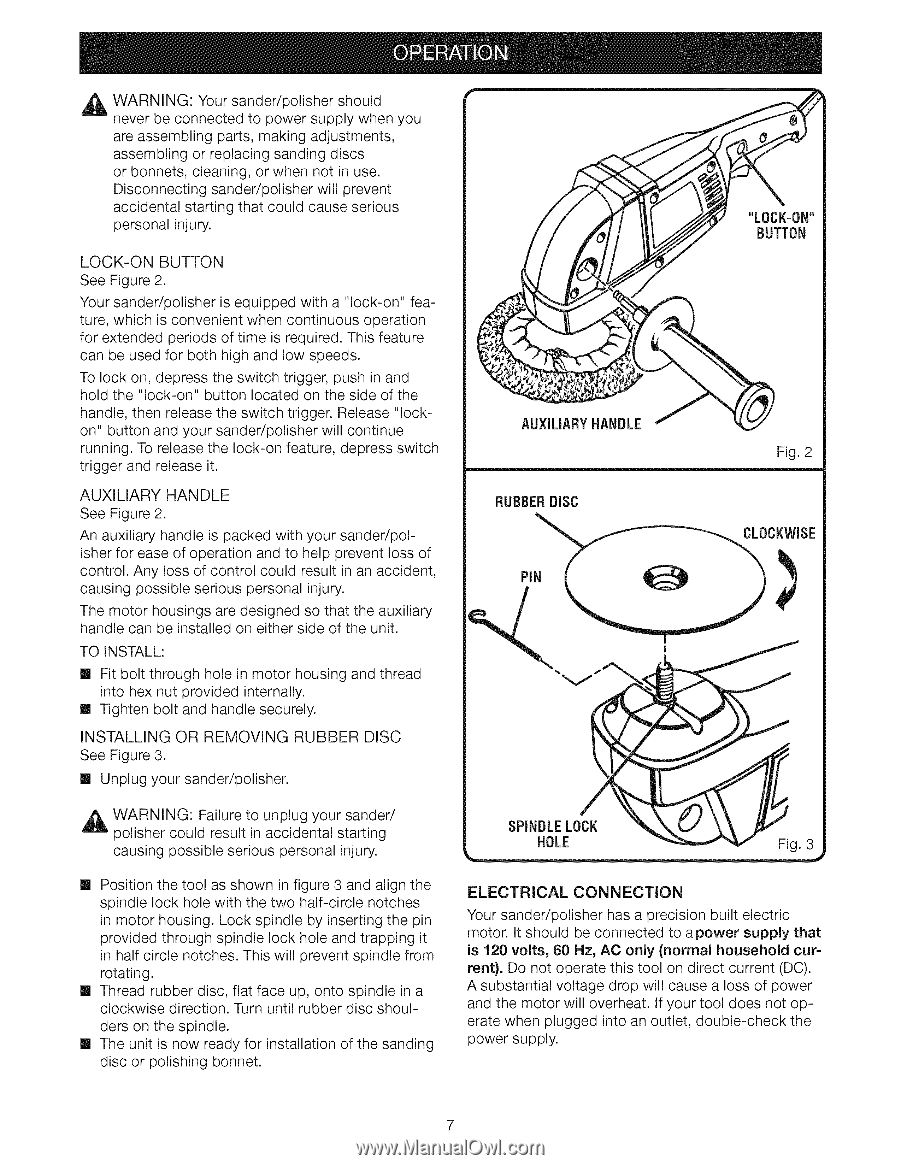
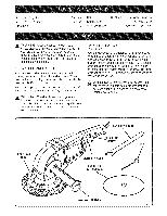
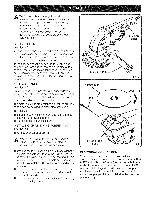
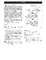
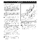
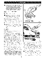
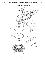
A WARNING: Your sander/polisher should never be connected to power supply when you are assembling parts, making adjustments, assembling or replacing sanding discs or bonnets, cleaning, or when not in use. Disconnecting sander/polisher will prevent accidental starting that could cause serious personal injury. LOCK-ON BUTTON See Figure 2. Your sander/polisher is equipped with a "lock-on" feature, which is convenient when continuous operation for extended periods of time is required. This feature can be used for both high and low speeds. To lock on, depress the switch trigger, push in and hold the "lock-on" button located on the side of the handle, then release the switch trigger. Release "lockon" button and your sander/polisher will continue running. To release the lock-on feature, depress switch trigger and release it. AUXILIARY HANDLE See Figure 2. An auxiliary handle is packed with your sander/polisher for ease of operation and to help prevent loss of control. Any loss of control could result in an accident, causing possible serious personal injury. The motor housings are designed so that the auxiliary handle can be installed on either side of the unit. TO INSTALL: [] Fit bolt through hole in motor housing and thread into hex nut provided internally. [] Tighten bolt and handle securely. INSTALLING OR REMOVING RUBBER DISC See Figure 3. [] Unplug your sander/polisher. AUXILIARY HANDLE Fig. 2 _1 WARNING: Failure to unplug your sander/ polisher could result in accidental starting causing possible serious personal injury. [] Position the tool as shown in figure 3 and align the spindle lock hole with the two half-circle notches in motor housing. Lock spindle by inserting the pin provided through spindle lock hole and trapping it in half circle notches. This will prevent spindle from rotating. [] Thread rubber disc, flat face up, onto spindle in a clockwise direction. Turn until rubber disc shoulders on the spindle. [] The unit is now ready for installation of the sanding disc or polishing bonnet. SPINDLELOCK HOLE Fig. 3 ELECTRICAL CONNECTION Your sander/polisher has a precision built electric motor. It should be connected to apower supply that is 120 volts, 60 Hz, AC only (normal household cur= rent). Do not operate this tool on direct current (DC). A substantial voltage drop will cause a loss of power and the motor will overheat. If your tool does not operate when plugged into an outlet, double-check the power supply.
-
 1
1 -
 2
2 -
 3
3 -
 4
4 -
 5
5 -
 6
6 -
 7
7 -
 8
8 -
 9
9 -
 10
10 -
 11
11 -
 12
12 -
13
-
14
 |
 |