Craftsman 21807 Operation Manual - Page 18
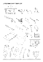
Stand Fig. - parts list
 |
View all Craftsman 21807 manuals
Add to My Manuals
Save this manual to your list of manuals |
Page 18 highlights
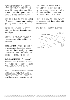
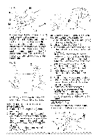
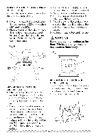
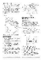
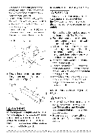
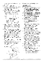
ASSEMBLE STAND (FIG. A, B, C) 1. Unpack all parts and group by type and size. Refer to the parts list for correct quantities. 2. Attach four hooks (10) to the top corner of the four legs (2) as shown. The hooks (10) are used to hold the dust bag. NOTE: Make sure the hook (10) is securely fastened to the corner of the leg (2). Fig. A _. .... 10 5. Assemble the other upper supports in exactly the same manner. 6. Attach one bottom support (5) to the center of the leg using bolt (3) and nut (4). This completes the front frame section. 7. Assemble rear frame section in exactly the same manner. 8. Join front-bottom and rear-bottom frame assemblies using the bottom support (7), bolts and nuts. Fig. C 3. Attach one long upper support with label (1) to top of leg (2) using one bolt (3) and nut (4). NOTE: o Align detents (8) in stand leg with support brackets to ensure proper fit. o Do not tighten bolts until stand is properly aligned. o Position all supports to the INSIDE of the leg assembles. 4. Attach short upper supports (6) to other hole of leg (2) using one bolt and nut. Fig. B Front ASSEMBLE THE ROLLER WHEEL TO STAND (FIG. D, E) 1. Place stand upside down on level surface or floor. 2. Place bottom support bracket for roller wheel (18) inner of the front leg (2). 3. Insert the bolt (12) through the roller wheel bracket (11), front leg (2), bottom support bracket (18) and nut (13) as shown. Tighten the nut. 4. Attach the roller wheel (14) to roller wheel bracket (11), bolt (15) and lock nut (16) using square neck bolt (15) and lock nut (16) as shown. NOTE: Do not overtighten nut as this will not allow the wheels to turn.
-
 1
1 -
2
-
3
-
4
-
5
-
6
-
7
-
8
-
9
-
10
-
11
-
12
-
 13
13 -
 14
14 -
 15
15 -
 16
16 -
 17
17 -
 18
18 -
 19
19 -
 20
20 -
 21
21 -
 22
22 -
 23
23 -
24
-
25
-
26
-
27
-
28
-
29
-
30
-
31
-
32
-
33
-
34
-
35
-
36
-
37
-
38
-
39
-
40
-
41
-
42
-
43
-
44
-
45
-
46
-
47
-
48
-
49
-
50
-
51
-
52
-
53
-
54
-
55
-
56
 |
 |
