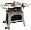
Craftsman 21807 Operation Manual - Page 24
in- 0.31in.3mm- 8 mm
 |
View all Craftsman 21807 manuals
Add to My Manuals
Save this manual to your list of manuals |
Page 24 highlights
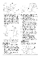
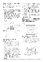
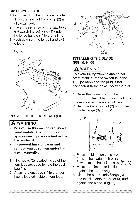
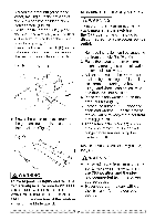
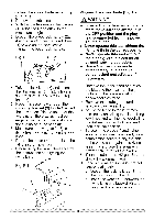
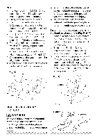
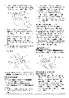
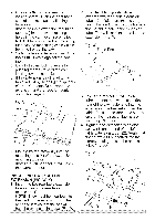
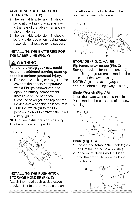
NOTE: o Thewashers(1/4"1/2-3/32(5) )are notincludedwiththistablesaw.It mustbepurchasesdeparately. o Rivingknifethicknessis 0.09in. o Themaximumradiadl istance betweentherivingknifeandthe toothedrimofthesawbladeis 0.12 in- 0.31in.(3 mm- 8 mm) o Thetipoftherivingknifeshallnot belowerthan0.04in._ 0.2in.(1 mm_ 5 mm)fromthetoothpeak. o Therivingknifeisthinnerthanthe widthofthe kerfbyapproximately 1/64inoneachside. 8. Checktherivingknifeandblade alignmenat gainatboth0° and45°. 9. Addor removethewashersuntilthe alignmenitscorrect. 10.Replactehetableinsertb, ladeguard andanti-kickbacpkawlassembly. Fig.Q 3 o When installing the blade guard, cover the blade teeth with a piece of folded cardboard to protect yourself from possible injury. o Never operate this machine without the blade guard in place for all through sawing operations. installing the blade guard and anti= kickback pawl assembly (Fig. R, S, T) 1. Make sure the blade is elevated to its maximum height and the bevel is set at 0 °. Make sure the bevel lock handle is tight. 2. Take the anti-kickback pawl assembly and lift up the locking lever (1) located on top. (Fig R) 3. Place the front of assembly into slot (2-Fig R) and push down making sure the assembly is engaged in the slots. There should be no movement of the assembly. Push down on the locking lever (1). (Fig S) 4 1 BLADEGUARDASSEMBLY (FIG.B,S,T) i_ WARNING] To avoid injury from an accidental start, make sure the switch is in the OFF position and the plug is disconnected from the power source outlet. Tighten
-
 1
1 -
2
-
3
-
4
-
5
-
6
-
7
-
8
-
9
-
10
-
11
-
12
-
13
-
14
-
15
-
16
-
17
-
18
-
 19
19 -
 20
20 -
 21
21 -
 22
22 -
 23
23 -
 24
24 -
 25
25 -
 26
26 -
 27
27 -
 28
28 -
 29
29 -
30
-
31
-
32
-
33
-
34
-
35
-
36
-
37
-
38
-
39
-
40
-
41
-
42
-
43
-
44
-
45
-
46
-
47
-
48
-
49
-
50
-
51
-
52
-
53
-
54
-
55
-
56
 |
 |
