Craftsman 21807 Operation Manual - Page 26
tubes2intothetwomatching
 |
View all Craftsman 21807 manuals
Add to My Manuals
Save this manual to your list of manuals |
Page 26 highlights
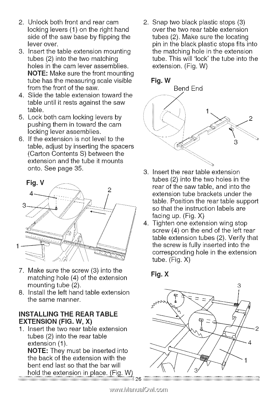
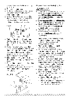
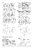
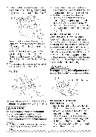
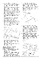
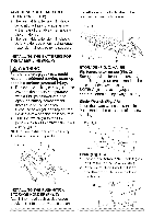
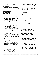
2. Unlockbothfrontandrearcam lockinglevers(1)ontherighthand sideof thesawbasebyflippingthe leverover. 3. Inserthetableextensionmounting tubes(2)intothetwomatching holesinthecamleverassemblies. NOTEM: akesurethefrontmounting tubehasthemeasurinsgcalevisible fromthefrontof thesaw. 4. Slidethetableextensiontowardthe . Snap two black plastic stops (3) over the two rear table extension tubes (2). Make sure the locating pin in the black plastic stops fits into the matching hole in the extension tube. This will 'lock' the tube into the extension. (Fig. W) Fig. W Bend End tableuntilit restsagainstthesaw table. 5. Lockbothcamlockingleversby pushingthemintowardthecam lockingleverassemblies. 6. Iftheextensionis notleveltothe table,adjustbyinsertingthespacers 3 (CartonContentsS) betweenthe extensionandthetubeit mounts onto.Seepage35. 3. Insert the rear table extension Fig. V tubes (2) into the two holes in the rear of the saw table, and into the extension tube brackets under the table. Position the rear table support so that the instruction labels are facing up. (Fig. X) 4. Tighten one extension wing stop screw (4) on the end of the left rear table extension tubes (2). Verify that the screw is fully inserted into the corresponding hole in the extension tube. (Fig. X) 7. Make sure the screw (3) into the matching hole (4) of the extension mounting tube (2). 8. Install the left hand table extension the same manner. Fig. X INSTALLING THE REAR TABLE EXTENSION (FIG. W, X) 1. Insert the two rear table extension tubes (2) into the rear table extension (1). NOTE: They must be inserted into the back of the extension with the bent end last so that the bar will
-
 1
1 -
2
-
3
-
4
-
5
-
6
-
7
-
8
-
9
-
10
-
11
-
12
-
13
-
14
-
15
-
16
-
17
-
18
-
19
-
20
-
 21
21 -
 22
22 -
 23
23 -
 24
24 -
 25
25 -
 26
26 -
 27
27 -
 28
28 -
 29
29 -
 30
30 -
 31
31 -
32
-
33
-
34
-
35
-
36
-
37
-
38
-
39
-
40
-
41
-
42
-
43
-
44
-
45
-
46
-
47
-
48
-
49
-
50
-
51
-
52
-
53
-
54
-
55
-
56
 |
 |