Craftsman 28928 Operation Manual - Page 22
on opposite
 |
View all Craftsman 28928 manuals
Add to My Manuals
Save this manual to your list of manuals |
Page 22 highlights
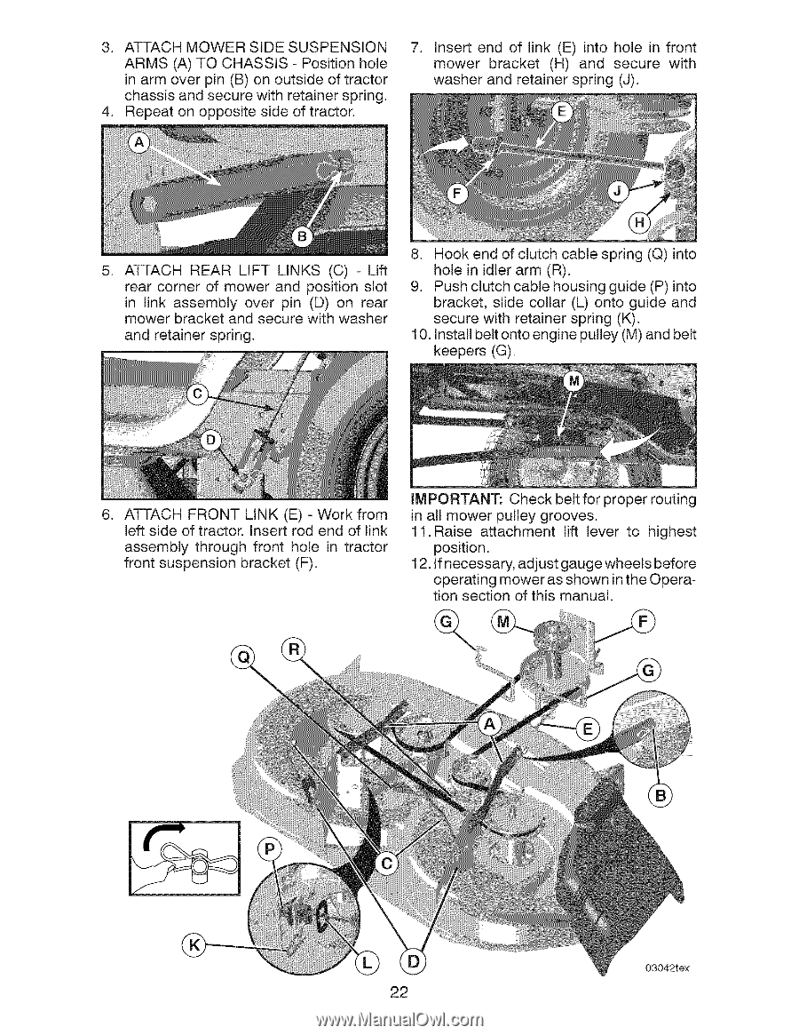
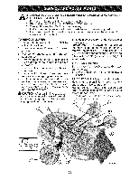
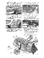
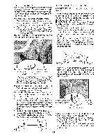
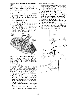
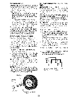
3. ATTACH MOWER SIDE SUSPENSION ARMS (A) TO CHASSIS - Position hole in arm over pin (B) on outside of tractor chassis and secure with retainer spring. 4. Repeat on opposite side of tractor. 7. Insert end of link (E) into hole in front mower bracket (H) and secure with washer and retainer spring (J). . ATTACH REAR LIFT LINKS (C) - Lift rear corner of mower and position slot in link assembly over pin (D) on rear mower bracket and secure with washer and retainer spring. 8. Hook end of clutch cable spring (Q) into hole in idler arm (R). 9. Push clutch cable housing guide (P) into bracket, slide collar (L) onto guide and secure with retainer spring (K). 10. Install belt onto engine pulley (M) and belt keepers (G). . ATTACH FRONT LINK (E) - Work from left side of tractor. Insert rod end of link assembly through front hole in tractor front suspension bracket (F). iMPORTANT: Check belt for proper routing in all mower pulley grooves. 11. Raise attachment lift lever to highest position. 12. If necessary, adjust gauge wheels before operating mower as shown in the Operation section of this manual. 03042tex 22
-
 1
1 -
2
-
3
-
4
-
5
-
6
-
7
-
8
-
9
-
10
-
11
-
12
-
13
-
14
-
15
-
16
-
 17
17 -
 18
18 -
 19
19 -
 20
20 -
 21
21 -
 22
22 -
 23
23 -
 24
24 -
 25
25 -
 26
26 -
 27
27 -
28
-
29
-
30
-
31
-
32
-
33
-
34
-
35
-
36
-
37
-
38
-
39
-
40
-
41
-
42
-
43
-
44
-
45
-
46
-
47
-
48
-
49
-
50
-
51
-
52
-
53
-
54
-
55
-
56
-
57
-
58
-
59
-
60
-
61
-
62
-
63
-
64
 |
 |