Craftsman 35182 Operation Manual - Page 19
See Chain Tension In Maintenance
 |
View all Craftsman 35182 manuals
Add to My Manuals
Save this manual to your list of manuals |
Page 19 highlights
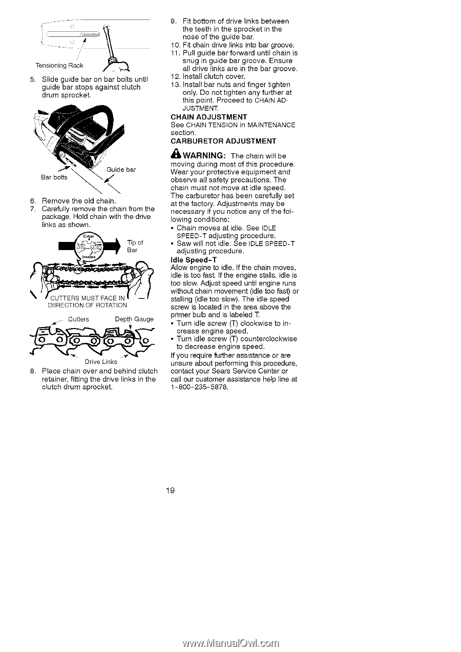
Tensioning RacI1'1k1 1_ 5. Slide guide bar on bar bolts until guide bar stops against clutch drum sprocket. _.r: Bar bolts Guide bar \ 6. Remove the old chain. 7. Carefully remove the chain from the package. Hold chain with the drive links as shown. _ ip of Bar D!IRECTION OF ROTATION _z Cutters Depth Gauge Drive Links 8. Place chain over and behind clutch retainer, fitting the drive links in the clutch drum sprocket. 9. Fit bottom of drive links between the teeth in the sprocket in the nose of the guide bar. 10. Fit chain drive links into bar groove. 11. Pull guide bar forward until chain is snug in guide bar groove. Ensure all drive links are in the bar groove. 12. Install clutch cover. 13. Install bar nuts and finger tighten only. Do not tighten any further at this point. Proceed to CHAIN ADJUSTMENT. CHAIN ADJUSTMENT See CHAIN TENSION in MAINTENANCE section. CARBURETOR ADJUSTMENT '_WARNING: The chain will be moving during most of this procedure. Wear your protective equipment and observe all safety precautions. The chain must not move at idle speed. The carburetor has been carefully set at the factory. Adjustments may be necessary if you notice any of the following conditions: • Chain moves at idle. See IDLE SPEED-T adjusting procedure. • Saw will not idle. See IDLE SPEED-T adjusting procedure. Idle Speed-T Allow engine to idle. If the chain moves, idle is too fast. If the engine stalls, idle is too slow. Adjust speed until engine runs without chain movement (idle too fast) or stalling (idle too slow). The idle speed screw is located in the area above the primer bulb and is labeled T • Turn idle screw (T) clockwise to increase engine speed. • Turn idle screw (T) counterclockwise to decrease engine speed. If you require further assistance or are unsure about performing this procedure, contact your Sears Service Center or call our customer assistance help line at 1-800-235-5878. 19
-
 1
1 -
2
-
3
-
4
-
5
-
6
-
7
-
8
-
9
-
10
-
11
-
12
-
13
-
 14
14 -
 15
15 -
 16
16 -
 17
17 -
 18
18 -
 19
19 -
 20
20 -
 21
21 -
 22
22 -
 23
23 -
 24
24
 |
 |