Craftsman 88690 Operation Manual - Page 23
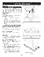
and9ft-lbs.
 |
View all Craftsman 88690 manuals
Add to My Manuals
Save this manual to your list of manuals |
Page 23 highlights
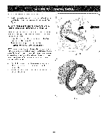
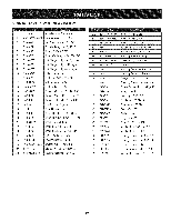
NOTEB:ecarefunlotodamagtheethreadosntheshaft, 7. Carefupllyositiothnehexshafdtownwaarnddtotheleftbefore carefusllylidintghefrictiownheealssembolfyftheshaftS. ee Figur3e1. NOTEIf:you'rreeplacitnhgefrictiownheealssembalsyawhole, discartdhewornparat ndslidethenewparot ntothehexshaft. FollotwhestepasbovienreversoerdetroreassemcbolemponenIfts. you'rdeisassembtlhinefgrictiownheealndreplacionnglytherubber ringp, roceeadsfollows: 1. Removtheefourscrewwshichsecurtehefrictiownheels'side platetsogetheSr.eeFigur3e2. 2. Removtheerubberirngfrombetweethneplates. 3. Reassemtbhleesideplatewsithanewrubberirng. NOTEW: herneassembtlhinegfrictiownheealssembmlya, kseure thatherubberirngiscentereadndseatepdroperblyetweethneside plateTs.ighteenachscrewonlyonerotatiobneforteurnintghewheel clockwiasendproceedwinigththenexst crewR.epeathtisprocess severtaiml estoensurteheplateasresecurewdithequafol rce (betwe6enft-lbasnd9ft-lbs). 4. Slidethefrictiownheealssembblaycokntothehexshafatnd followthestepasbovienreversoerdetroreassemble components. 5. PerfortmheDrivCe ontrTolesot utlineedarlieinrtheServicaend Maintenasneccetion. Figur3e1 ... j Figure32 23
-
 1
1 -
2
-
3
-
4
-
5
-
6
-
7
-
8
-
9
-
10
-
11
-
12
-
13
-
14
-
15
-
16
-
17
-
 18
18 -
 19
19 -
 20
20 -
 21
21 -
 22
22 -
 23
23 -
 24
24 -
 25
25 -
 26
26 -
 27
27 -
 28
28 -
29
-
30
-
31
-
32
-
33
-
34
-
35
-
36
-
37
-
38
-
39
-
40
-
41
-
42
-
43
-
44
-
45
-
46
-
47
-
48
-
49
-
50
-
51
-
52
-
53
-
54
-
55
-
56
-
57
-
58
-
59
-
60
-
61
-
62
-
63
-
64
-
65
-
66
-
67
-
68
-
69
-
70
-
71
-
72
 |
 |
