Creative SB0350 Hardware Programming Guide - Page 19
Creative SB0350 Manual
 |
View all Creative SB0350 manuals
Add to My Manuals
Save this manual to your list of manuals |
Page 19 highlights
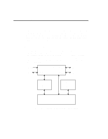
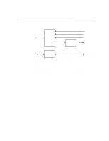
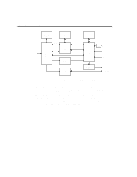
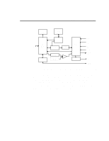
1-6 Hardware Overview Block Diagrams for Sound Blaster Family of Audio Cards After presenting the introduction to the major building blocks of Sound Blaster cards, we will now present the block diagrams for SB2.0, SB2CD, SBPRO and SB16. JOYSTICK PORT MIDI PORT COMMAND/ DATA CT1351 DSP CT1336 BUS INTERFACE CHIP CONTROL AD/DA FILTER AGC MIC LINE IN ISA BUS FM SYNTHESIZER POWER AMP. SPKR CMS Figure 1-2: Block Diagram of the Sound Blaster 2.0 Note that the CMS chip is optional. The CMS uses Pulse Width Modulation (PWM) technique to synthesize music. The quality of the sound is not as good as that from a FM synthesizer, and therefore, has been gradually phased out. All Sound Blaster cards that is later than SB2.0 does not have the CMS upgrade socket. Please note the SB2.0 does not contain a mixer chip on board.
-
 1
1 -
2
-
3
-
4
-
5
-
6
-
7
-
8
-
9
-
10
-
11
-
12
-
13
-
 14
14 -
 15
15 -
 16
16 -
 17
17 -
 18
18 -
 19
19 -
 20
20 -
 21
21 -
 22
22 -
 23
23 -
 24
24 -
25
-
26
-
27
-
28
-
29
-
30
-
31
-
32
-
33
-
34
-
35
-
36
-
37
-
38
-
39
-
40
-
41
-
42
-
43
-
44
-
45
-
46
-
47
-
48
-
49
-
50
-
51
-
52
-
53
-
54
-
55
-
56
-
57
-
58
-
59
-
60
-
61
-
62
-
63
-
64
-
65
-
66
-
67
-
68
-
69
-
70
-
71
-
72
-
73
-
74
-
75
-
76
-
77
-
78
-
79
-
80
-
81
-
82
-
83
-
84
-
85
-
86
-
87
-
88
-
89
-
90
-
91
-
92
-
93
-
94
-
95
-
96
-
97
-
98
-
99
-
100
-
101
-
102
-
103
-
104
-
105
-
106
-
107
-
108
-
109
-
110
-
111
-
112
-
113
-
114
-
115
-
116
-
117
-
118
-
119
-
120
-
121
-
122
-
123
-
124
-
125
-
126
-
127
-
128
-
129
-
130
-
131
-
132
-
133
-
134
-
135
-
136
-
137
-
138
-
139
-
140
-
141
 |
 |
