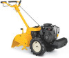
Cub Cadet RT 65 H Garden Tiller Operation Manual - Page 9
Set-Up, Adjustments
 |
View all Cub Cadet RT 65 H Garden Tiller manuals
Add to My Manuals
Save this manual to your list of manuals |
Page 9 highlights
Control Rod 1. Make sure the handle assembly is in the highest position. Refer to the Controls & Features section. 2. Remove the cotter pins from the control rod, leave the rubber washers on the control rod. See Figure 3-6. Cotter Pin Rubber Washers Cotter Pin Figure 3-6 3. Insert the shorter (angled) end of the control rod through the indicator bracket on the shift cover and secure with the cotter pin that was previously removed. See Figure 3-7. Rubber Washers Cotter Pin Gear Selector Handle Cotter Pin Set-Up Tires The tires on the tiller may be over-inflated for shipping purposes. Reduce the tire pressure before operating the tiller. Recommended operating tire pressure is approximately 20 PSI (check the sidewall of the tire for the manufacturer's recommended pressure). Be sure that both tires are inflated equally or the tiller will pull to one side. Gas & Oil Fill-Up Service the engine with gasoline and oil as instructed in the separate Engine Operator's Manual packed with your tiller. Read the instructions carefully. WARNING! Use extreme care when handling gasoline. Gasoline is extremely flammable and the vapors are explosive. Never fuel the machine indoors or while the engine is hot or running. Adjustments Clutch Cable NOTE: Service the engine with oil and gasoline before checking this adjustment. Refer to the separate Engine Operator's Manual packed with your tiller for proper fuel and engine oil recommendations. 1. Position the tiller so the front counterweight is against a solid object, such as a wall. 2. With the gear selection lever in NEUTRAL, start the engine. Refer to the separate Engine Operator's Manual. 3. Standing on the right side of the tiller, examine the belt (inside the belt cover). It should not be turning. WARNING! Do not put your fingers under the belt cover. 4. If the belt turns without bail engaged, adjust it by unthreading the internally threaded tube at the end of the cable a few turns clockwise (when standing in the operator's position) and then retighten the nut against the tube. 5. Move the shift lever to the FORWARD position. Rubber Washers Indicator Bracket Figure 3-7 4. Insert the longer end of the control rod through the hole in the gear selector handle and secure with the cotter pin. See Figure 3-7. Section 3 - Assembly & Set-Up 9
-
 1
1 -
2
-
3
-
 4
4 -
 5
5 -
 6
6 -
 7
7 -
 8
8 -
 9
9 -
 10
10 -
 11
11 -
 12
12 -
 13
13 -
 14
14 -
15
-
16
-
17
-
18
-
19
-
20
-
21
-
22
-
23
-
24
-
25
-
26
-
27
-
28
-
29
-
30
-
31
-
32
-
33
-
34
-
35
-
36
-
37
-
38
-
39
-
40
 |
 |
