Cub Cadet RT 65 Rear Tine Tiller Operation Manual - Page 7
Assembly & Set-Up - depth stake
 |
View all Cub Cadet RT 65 Rear Tine Tiller manuals
Add to My Manuals
Save this manual to your list of manuals |
Page 7 highlights
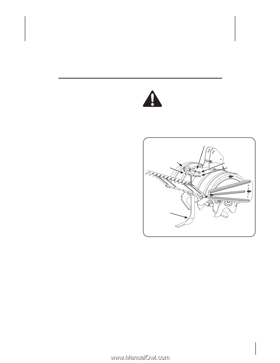
Assembly & Set-Up 3 Contents of Carton • One Tiller • One Depth Stake • One Handlebar Assembly • One Operator's Manual • One Shift Rod • One Engine Operator's Manual Assembly Unpacking Instructions NOTE: References to the right or left side of the tiller are determined from behind the machine in the operating position. 1. Remove the staples, break the glue on the top flaps, or cut the tape at the end of the carton and peel it along the top flap to open. 2. Remove any loose parts included with the tiller (i.e., the Operator's Manual, etc.). 3. Cut the corners and lay the carton down flat. 4. Remove the packing material. 5. Roll or slide the tiller out of the carton. Check the carton thoroughly for loose parts. 6. Extend the control cable and lay it on the floor. Be careful not to bend or kink the control cable. NOTE: This machine is shipped without gasoline or oil in the engine. Be certain to service the engine with gasoline and oil as instructed in the separate Engine Operator's Manual before operating. Depth Stake WARNING! Before assembly, disconnect the spark plug wire and ground it against the engine to prevent unintended starting. 1. Tip the tiller forward so that it rests on the front counterweight. 2. Unthread the "T" knob from the top of the depth stake and remove the flat washer and hex bolt. Remove the cotter pin from the clevis pin. See Fig. 3-1. Flat Washer T-Knob Clevis Pin Hex Bolt Cotter Pin Depth Stake Figure 3-1 3. Raise the tine shield hinge flap assembly and insert the depth stake assembly in the slot, under the tine shield and up through the tine shield assembly. 4. Insert the clevis pin through the tine shield and depth stake assemblies. Secure it with the cotter pin. 5. Insert the hex bolt into the top hole of the depth stake assembly. Place the flat washer on the hex bolt and thread the T-knob onto the hex bolt. Tighten securely. See Fig. 3-1. 6. Tip the tiller back down so that it rests on the tines. 7
-
 1
1 -
 2
2 -
 3
3 -
 4
4 -
 5
5 -
 6
6 -
 7
7 -
 8
8 -
 9
9 -
 10
10 -
 11
11 -
 12
12 -
13
-
14
-
15
-
16
-
17
-
18
-
19
-
20
-
21
-
22
-
23
-
24
 |
 |