Cub Cadet RT 65 Rear Tine Tiller Operation Manual - Page 9
Adjustments
 |
View all Cub Cadet RT 65 Rear Tine Tiller manuals
Add to My Manuals
Save this manual to your list of manuals |
Page 9 highlights
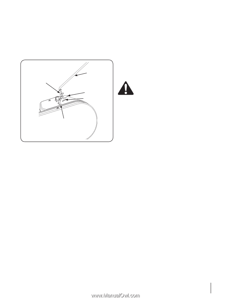
Control Rod 1. Make sure the handle assembly is in the highest position. Refer to the Controls & Features Section. 2. Remove the hairpin clips from the control rod, put the rubber washers in place. 3. Insert the shorter, angled end of the control rod through the indicator bracket on the shift cover and secure it with the previously removed hairpin clip. See Fig. 3-5. Rubber Washer Control Rod Indicator Bracket Cotter Pin Idler Pulley Rod Figure 3-5 4. Insert the longer end of the control rod through the hole in the gear selector handle and secure with a cotter pin. Adjustments Clutch Cable NOTE: Service the engine with oil and gasoline before checking this adjustment. Refer to the separate Engine Operator's Manual packed with your tiller for proper fuel and engine oil recommendations. 1. Position the tiller so the front counterweight is against a solid object, such as a wall. 2. With the gear selection lever in NEUTRAL, start the engine. Refer to the separate Engine Operator's Manual. 3. Standing on the right side of the tiller, examine the belt (inside the belt cover). It should not be turning. wARNING! Do not put your fingers under the belt cover. 4. If the belt turns without the bail engaged, adjust it by unthreading the internally threaded tube at the end of the cable a few turns clockwise - when standing in the operator's position - and then retighten the nut against the tube. 5. Now move the shift lever to the FORWARD position. 6. Carefully engage the clutch by lifting the clutch control bail against the handle. The wheels should spin. 7. If the wheels do not spin with the tiller in forward, adjust by unthreading the tube at the end of the cable a few turns counter-clockwise - when standing in operator's position - and then retighten the nut against the tube. 8. Recheck both adjustments, and readjust as necessary. NOTE: A secondary cable adjustment is available if you reach the point that additional adjustment is needed. Remove the belt cover and move the hex nuts at the other end of the cable towards the end of the casing. Then readjust the hex nuts at the handle. Section 3 - Assembly & Set-Up 9
-
 1
1 -
2
-
3
-
 4
4 -
 5
5 -
 6
6 -
 7
7 -
 8
8 -
 9
9 -
 10
10 -
 11
11 -
 12
12 -
 13
13 -
 14
14 -
15
-
16
-
17
-
18
-
19
-
20
-
21
-
22
-
23
-
24
 |
 |