Cub Cadet TANK L 60 KH TANK L 60 KH Operator's Manual - Page 12
Install Roll Over Protective System ROPS
 |
View all Cub Cadet TANK L 60 KH manuals
Add to My Manuals
Save this manual to your list of manuals |
Page 12 highlights
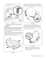
5. To release the parking brake, flip the seat forward and locate Install Roll Over Protective System (ROPS) the cotter pin and clevis pin that secure the dump valve relief lever to the parking break handle. See Figure 3-3. The Roll Over Protective System (ROPS) has not been installed on your unit for shipping purposes. Using the hardware found in the Roll Over Protective System container, install it on your unit as follows: 1. Insert each of the lower section ROPS tubular posts into the brackets welded to the tractor main frame. See Figure 3-4. Clevis Pin ROPS Lower Sections Dump Valve Relief Lever Cotter Pin Figure 3-3 6. Remove the cotter pin from the clevis pin. Then slide the clevis pin out of the relief lever. Be sure not to lose the spacer on the inside of the relief lever. 7. With the dump valve relief lever free from the parking break cable, release the parking brake and the tractor will now move in freewheel mode. 2. WARNING! Do not tow the tractor, even with the bypass valves engaged. Serious transmission damage will result from doing so. 8. Carefully roll the tractor off the shipping pallet. 9. Reset the parking brake, and resintall the clevis pin, spacer, 3. cotter pin and dump valve relief lever back onto the parking brake handle. 10. Remove the deck wash system nozzle adapter from the manual bag and store for future use. Cut the wire tie holding the chute deflector up and discard any packing material. Flat Washer Carriage Bolt Flange Lock Nut Flat Washer Reinforced Plate Figure 3-4 Insert the hex screws (one per side) through the flat washer then into the frame brackets and ROPS posts from the rear toward the front. See Figure 3-4. Alternately from the front toward the rear if access is restricted. NOTE: The mounting hardware is accessible from the rear of the machine with the use of extensions. Also, access can be gained by reaching in from the sides over the tires fuel tanks. Install the reinforced plates and flange lock nuts, but do not tighten. See Figure 3-4. 12 Section 2- Assembly & Set-Up
-
 1
1 -
2
-
3
-
4
-
5
-
6
-
 7
7 -
 8
8 -
 9
9 -
 10
10 -
 11
11 -
 12
12 -
 13
13 -
 14
14 -
 15
15 -
 16
16 -
 17
17 -
18
-
19
-
20
-
21
-
22
-
23
-
24
-
25
-
26
-
27
-
28
-
29
-
30
-
31
-
32
-
33
-
34
-
35
-
36
-
37
-
38
-
39
-
40
-
41
-
42
-
43
-
44
 |
 |
