Cub Cadet TANK L 60 KH TANK L 60 KH Operator's Manual - Page 14
Installing the Seat
 |
View all Cub Cadet TANK L 60 KH manuals
Add to My Manuals
Save this manual to your list of manuals |
Page 14 highlights
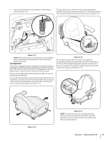
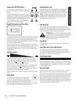
To adjust the height of the drive control levers: 1. Remove the flange lock nuts that secure the carriage bolts in the drive control levers. See Figure 3-8. 3. From the inside insert the carriage boltthrough the control lever slot and the hole of the pivot bracket. Secure with the flange lock nut. See Figure 3-9. 4. Note the relative position of the control lever to the pivot bracket, then repeat the previous steps to reposition the other control lever in approximately the same position. 5. Refer to "Adjusting the Drive Control Levers" in the Maintenance & Adjustments for instructions on the final adjustment of the levers. Installing the Seat 1. Remove the two flange lock nuts and shoulder bolts from the seat bracket. See Figure 3-10. Flange Lock Nuts Carriage Bolts Figure 3-8 2. Remove the carriage bolts from the drive control levers and reposition to the second set of holes in the mounting block. 3. Reinstall the carriage bolts and flange lock nuts, and tighten to 28-34 ft-lbs. 4. The same adjustments should be made to both sides of the mower. To adjust the front-to-rear angle of the drive control levers: 1. Remove the carriage bolt and flange lock nut from the slot of one of the drive control levers. 2. 2. Lift and swing that control lever upward until the slotted hole in the lever bracket aligns with one of the holes in the pivot bracket. See Figure 3-9. 3. Figure 3-10 Place the seat into position and secure the seat into place with the previously removed hardware as shown in Figure 3-10. Remove the shoulder screw and flange lock nut from the the support cable and install the support cable with the previously removed hardware. See Figure 3-11. Figure 3-9 14 Section 2- Assembly & Set-Up Figure 3-11
-
 1
1 -
2
-
3
-
4
-
5
-
6
-
7
-
8
-
 9
9 -
 10
10 -
 11
11 -
 12
12 -
 13
13 -
 14
14 -
 15
15 -
 16
16 -
 17
17 -
 18
18 -
 19
19 -
20
-
21
-
22
-
23
-
24
-
25
-
26
-
27
-
28
-
29
-
30
-
31
-
32
-
33
-
34
-
35
-
36
-
37
-
38
-
39
-
40
-
41
-
42
-
43
-
44
 |
 |
