Cub Cadet TANK M72-KW TANK M72-KW Operator's Manual - Page 10
Assembly & Set-Up
 |
View all Cub Cadet TANK M72-KW manuals
Add to My Manuals
Save this manual to your list of manuals |
Page 10 highlights
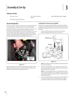
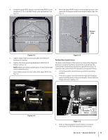
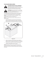
Assembly & Set-Up 3 Contents of Crate • One Lawn Tractor • One Engine Operator's Manual • One Tractor Operator's Manual • One Deck Wash Hose Coupler Tractor Preparation Remove the upper crating material from the shipping pallet, and cut any bands or tie straps securing the tractor to the pallet. Use the lift handle to raise the deck to its highest position. Locate the valves on the hydraulic pump. Turn the valves counterclockwise (using a standard 7⁄16" wrench) one quarter turn to push the unit off the crate. After pushing the mower to the desired location, return both valves to the operating position by turning the valve clockwise, but do not overtighten. See Fig. 3-1. Install Roll Over Protective System (ROPS) The Roll Over Protective System (ROPS) has not been installed on your unit for shipping purposes. Using the hardware found in the Roll Over Protective System container, install it on your unit as follows: 1. Insert each of the lower section ROPS posts into the brackets welded to the main frame. See Fig. 3-2. ROPS Posts Washer Nut Carriage Bolts Transmission Bypass Valve Figure 3-1 Remove the deck wash system nozzle adapter from the manual bag and store for future use. Cut the wire tie holding the chute deflector up and discard any packing material. Frame Brackets Figure 3-2 NOTE: The ROPS pivot holes should be positioned toward the rear of the tractor. 2. Insert the carriage bolts (1⁄2-13 x 3.00) (two per side) from the front toward the rear. Alternately from the rear toward the front if access is restricted. NOTE: The mounting hardware is accessible from the rear of the machine with the use of extensions. Also, access can be gained by reaching in from the sides over the tires and under the fuel tanks. 3. Three holes are provided on each side. Use the Upper hole and one of the other two remaining holes that is easily accessible. Install the retaining nuts, but do not tighten. 10
-
 1
1 -
2
-
3
-
4
-
 5
5 -
 6
6 -
 7
7 -
 8
8 -
 9
9 -
 10
10 -
 11
11 -
 12
12 -
 13
13 -
 14
14 -
 15
15 -
16
-
17
-
18
-
19
-
20
-
21
-
22
-
23
-
24
-
25
-
26
-
27
-
28
-
29
-
30
-
31
-
32
-
33
-
34
-
35
-
36
-
37
-
38
-
39
-
40
-
41
-
42
-
43
-
44
-
45
-
46
-
47
-
48
 |
 |
