Cub Cadet TANK M72-KW TANK M72-KW Operator's Manual - Page 11
Position Drive Control levers
 |
View all Cub Cadet TANK M72-KW manuals
Add to My Manuals
Save this manual to your list of manuals |
Page 11 highlights
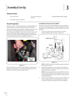
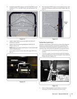
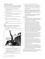
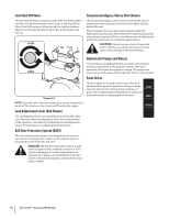
4. Install the upper ROPS section onto the lower ROPS "posts". 8. Move the upper ROPS section to the upright position, and Install the (1⁄2-13 x 3.25) HHCS bolts, nuts and washers. See insert the locking pins with their retainer hairpin clips. See Fig. 3-3. Fig. 3-5. Hex Bolts Washers Nuts Lower ROPS Posts Locking Pin Hairpin Clips Figure 3-3 Figure 3-5 5. Tighten Upper ROPS section bolts after both RH & LH hardware is installed. Position Drive Control levers 6. Tighten the frame mounting hardware to 80-90 lb.-ft. The drive control levers of the tractor are lowered for shipping torque. See Fig. 3-2. purposes. Using the hardware found in the manual bag, the NOTE: Make sure tubular upright posts are absolutely tight control levers must be repositioned to operate the tractor. To within welded bracket. reposition the control levers for operation, proceed as follows: 7. Insert rubber plugs into each side of the upper ROPS. See Fig. 3-4. 1. Lift and swing the control levers up into the operating position. 2. From the outside, insert the bolts through the hourglass spacers and the holes of the pivot bracket. Secure with the flange lock nuts. See Fig. 3-6. Rubber Plug Figure 3-4 Bolt Nut Hourglass Spacer Figure 3-6 3. Refer to "Adjusting Drive Control Levers" section for instructions on the final adjustment of the levers. Section 2 - Assembly & Set-Up 11
-
 1
1 -
2
-
3
-
4
-
5
-
 6
6 -
 7
7 -
 8
8 -
 9
9 -
 10
10 -
 11
11 -
 12
12 -
 13
13 -
 14
14 -
 15
15 -
 16
16 -
17
-
18
-
19
-
20
-
21
-
22
-
23
-
24
-
25
-
26
-
27
-
28
-
29
-
30
-
31
-
32
-
33
-
34
-
35
-
36
-
37
-
38
-
39
-
40
-
41
-
42
-
43
-
44
-
45
-
46
-
47
-
48
 |
 |
