Cub Cadet XT1 LT42 with IntelliPower Operation Manual - Page 19
Lubricating Pivot Points & Linkage
 |
View all Cub Cadet XT1 LT42 with IntelliPower manuals
Add to My Manuals
Save this manual to your list of manuals |
Page 19 highlights
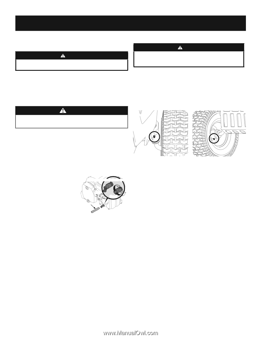
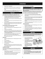
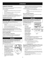
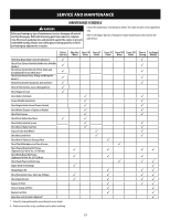
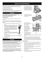
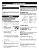
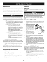
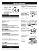
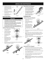
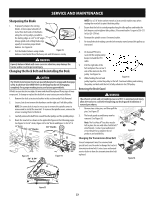
SERVICE AND MAINTENANCE Maintenance Lubrication Engine WARNING WARNING Allow machine to cool in an open area for at least five minutes before storing or refueling. Refer to the Engine Operator's Manual for all engine issues and questions. Note : Maintenance, repair, or replacement of the emission control devices and systems which are being done at owner's expense may be performed by any engine repair establishment or individual. Warranty repairs must be performed by an authorized dealer. Changing the Engine Oil WARNING Before lubricating, repairing, or inspecting, always disengage PTO, set parking brake, stop engine and remove key to prevent unintended starting. Using a quality lubricating oil, lubricate all lubrication points. Refer to maintenance schedule chart located in this manual for proper service intervals. Lubricating Front Wheels Each of the front wheel axles and rims is equipped with a grease fitting. See Figure 36 for the location of the grease fitting on the axles and Figure 37 for the location of the grease fitting on the rims. Lubricate with a No. 2 multi-purpose grease applied with a grease gun per the Maintenance Schedule. If the tractor has been recently run, the engine, muffler and surrounding metal surfaces will be hot and can cause burns to the skin. Let the engine cool for at least five minutes. Exercise caution to avoid burns. NOTE: The oil filter should be changed at every oil change interval. To complete an oil change, proceed as follows: 1. Run the engine for a short time to warm the engine oil. The oil will flow more freely and carry away more impurities. Use care to avoid burns from hot oil. 2. Open the tractor's hood and locate the oil drain port on the side of the engine. 3. Place an appropriate oil collection container with at least a 2.5 quart (2.36L) Figure 36 Figure 37 capacity below the opening of the oil drain tube, to collect the used oil. Remove the oil fill cap/dipstick from the Lubricating Deck Wheels oil fill tube. Rotate Counterclockwise to open The wheels on the deck which are spherical shaped (50" and 54" decks have 4) are 4. Open the protective cap on the end of equipped with a grease fitting. Lubricate with a No. 2 multi-purpose grease applied the oil drain valve to expose the drain Open with a grease gun per the Maintenance Chart. port. See Figure 35. 5. Push the oil drain tube (packed with Clear Oil this manual) onto the oil drain port. Drain Tube Closed Lubricating Pivot Points & Linkage Lubricate all the pivot points on the drive system, parking brake and lift linkage per Route the opposite end of the tube into the Maintenance Chart. an appropriate oil collection container with at least a 2.5 quart (2.36L) capacity to collect the used oil. Figure 35 NOTE: It is not necessary to grease the steering pinion/sector gear interface. Doing so will allow dirt to accumulate and can affect steering performance. 6. The engine is equipped with a twist-and-pull drain port. Turn the oil drain Hydrostatic Transmission valve 1⁄4-turn counter-clockwise, then pull outward to begin draining oil. After the oil has finished draining, push the end of the oil drain valve back in and turn 1⁄4-turn clockwise to close the oil drain. Re-cap the end of the oil drain valve to keep debris from entering the drain port. The hydrostatic transmission is sealed at the factory and is maintenance-free. The fluid level cannot be checked and the fluid cannot be changed. Spark Arrestor Maintenance (If Equipped) 7. Replace the oil filter, and refill the engine with new oil as instructed in the engine operator's manual. 8. Reinstall the oil fill cap/dipstick. Spark arrestor assemblies must be inspected and cleaned periodically (see the service interval chart in this manual). Visually inspect the screen for tears, broken wires or loose welds. Replace the spark arrestor assembly if any of these conditions exist. If the screen is in good condition, clean the screen by brushing away loose dirt or carbon particles. NOTE: Place an absorbent towel beneath the oil filter to keep oil off the engine pulley. Tires NOTE: Observe proper disposal laws and regulations for gas, oil, etc. to protect the environment. NOTE: Maintenance, repair, or replacement of the emission control devices and systems which are being done at the owner's expense may be performed by any engine repair establishment or individual. Warranty repairs must be performed by an authorized dealer. Keep the tires inflated to the recommended pressures. Improper inflation will shorten the tire service life. See the tire side wall for proper inflation pressures. Refer to maintenance schedule chart located in this manual for proper service intervals. Observe the following guidelines: • Do not inflate a tire above the maximum pressure shown on the sidewall of the tire. • Do not reinflate a tire that has been run flat or seriously under inflated. Have it inspected and serviced by a qualified tire mechanic. 19
-
 1
1 -
2
-
3
-
4
-
5
-
6
-
7
-
8
-
9
-
10
-
11
-
12
-
13
-
 14
14 -
 15
15 -
 16
16 -
 17
17 -
 18
18 -
 19
19 -
 20
20 -
 21
21 -
 22
22 -
 23
23 -
 24
24 -
25
-
26
-
27
-
28
-
29
-
30
-
31
-
32
-
33
-
34
-
35
-
36
-
37
-
38
-
39
-
40
-
41
-
42
-
43
-
44
-
45
-
46
-
47
-
48
-
49
-
50
-
51
-
52
-
53
-
54
-
55
-
56
-
57
-
58
-
59
-
60
-
61
-
62
-
63
-
64
-
65
-
66
-
67
-
68
-
69
-
70
-
71
-
72
 |
 |