Cub Cadet Z-Force SX 48 Operation Manual - Page 8
Transmission Oil Expansion, Reservoir
 |
View all Cub Cadet Z-Force SX 48 manuals
Add to My Manuals
Save this manual to your list of manuals |
Page 8 highlights
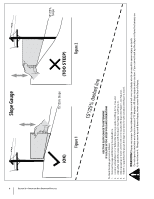
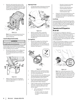
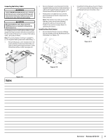
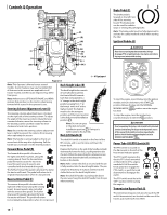
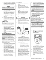
3. Rotate the seat into position and secure the seat into place with the previously removed shoulder screws and flange lock nuts. Be careful not to crimp or damage the wire harness while installing the seat. See Figure 2-4. Adjusting the Seat 1. To adjust the position of the seat, push the seat adjustment lever to the left. See Figure 2-6. 2 (a) (b) (b) (c) (a) Figure 2-4 Note: Be sure to push the excess wire from the wire harness into the seat box hole before continuing. Lower Discharge Chute Assembly WARNING Never operate the tractor deck without the discharge chute assembly installed and in the down position. The discharge chute assembly must be installed before operating the tractor. To install the discharge chute assembly, proceed as follows: 1. Remove the carriage screws (a), flange lock nuts (b) and flat washers (c) installed on the mounting bracket (d) on the deck. See Figure 2-5. 1 Figure 2-6 2. Slide the seat forward or rearward to the desired position; then release the adjustment lever. Make sure seat is locked into position before operating the tractor. See Figure 2-6. Steering Wheel 1. Remove the hardware for attaching the steering wheel (a) from beneath the steering wheel cover (b). Carefully pry off the steering wheel cover (b) to remove the hardware. See Figure 2-7. (e) (b) (a) (d) (e) (d) • Operator's forearms should be approximately horizontal. • Operator's back should stay in contact with the seat back. • Steering column should not contact operator's legs. 6. Check the results of any adjustments to the conditions described above. Repeat any adjustment procedures as required until all conditions are met. Fuel Fill-Up Using a good grade of unleaded regular gasoline, fill the tank (beside the engine on the right side of the mower). When the fuel tank reaches one inch from the top of the tank, stop, DO NOT OVERFILL. Space must be left for expansion. Transmission Oil Expansion Reservoir The transmission oil expansion reservoir is connected by hoses to the RH and LH transmission assemblies, and is located behind the seat box. The function of the reservoir is to hold the natural expansion of transmission oil that occurs as the transmission warms up during operation. DO NOT FILL THE RESERVOIR. Under normal operating conditions, no oil should be added to the reservoir. The COLD oil level should be no higher than approximately 1⁄4" (the "Full Cold" mark) above the bottom of the reservoir. See Figure 2-8. (d) (b) (b) (d) (c) (a) (c) (a) Figure 2-5 2. With the previously removed hardware, install the chute deflector on the deck as shown in Figure 2-5. (c) Figure 2-7 2. With the wheels of the machine pointing straight forward, place the steering wheel (a) over the steering shaft (c). 3. Place the belleville washer (d) with the cupped side facing inward over the steering wheel and secure with the hex lock screw (e). 4. Place the steering wheel cover (b) over the center of the steering wheel (a) and push downward until it "clicks" into place. 5. Proper steering column and seat adjustment will result in the following (to adjust the seat, refer to Adjusting the Seat on the previous page): a. In the neutral position with hands on the steering wheel, • Operator's upper arms should be relaxed and approximately vertical. Figure 2-8 Note: Prior to the initial operation of the tractor, the oil level in the reservoir may be slightly higher than the maximum due to air in the oil lines. Operation of the tractor will eventually purge the air from the lines and the oil level will settle to the maximum. 8 Section 2 - Assembly & Set-Up
-
 1
1 -
2
-
 3
3 -
 4
4 -
 5
5 -
 6
6 -
 7
7 -
 8
8 -
 9
9 -
 10
10 -
 11
11 -
 12
12 -
 13
13 -
14
-
15
-
16
-
17
-
18
-
19
-
20
-
21
-
22
-
23
-
24
-
25
-
26
-
27
-
28
-
29
-
30
-
31
-
32
-
33
-
34
-
35
-
36
-
37
-
38
-
39
-
40
-
41
-
42
-
43
-
44
 |
 |
