Cub Cadet ZT2 54 Operation Manual - Page 20
Adjustments
 |
View all Cub Cadet ZT2 54 manuals
Add to My Manuals
Save this manual to your list of manuals |
Page 20 highlights
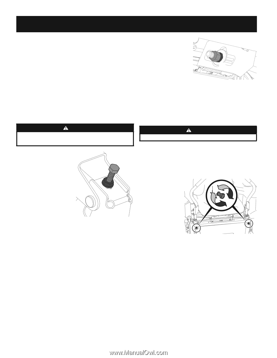
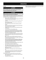
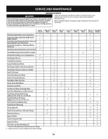
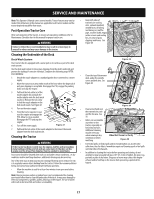
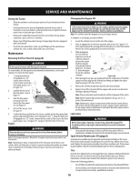
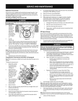
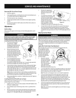
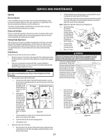
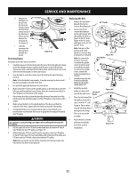
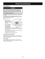
SERVICE AND MAINTENANCE Removing The Tractor From Storage 1. Check the engine oil. 2. Fully charge the battery and inflate the tires to the recommended pressure. See tire side wall for proper tire inflation pressure. 3. Fill the fuel tank with clean, fresh gasoline. 4. Start the engine and allow to idle for a few minutes to ensure engine is operating properly. 5. Drive the tractor without a load to make certain all the tractor systems are functioning properly. Adjustments Deck Leveling If the cutting deck appears to be mowing unevenly, leveling adjustments can be performed. WARNING If the tractor has been recently run, the engine, muffler and surrounding metal surfaces will be very hot and can cause burns to the skin. Let the engine cool for at least five minutes. Exercise caution to avoid burns. Leveling the Deck (Side-to-Side) 1. Place the deck lift handle or deck lift knob in a middle mowing position and rotate both outside blades so that they are (a) perpendicular with the tractor. 2. Measure the distance from the outside of the left blade tip to the ground and the distance from the (b) outside of the right blade tip to the ground. Both measurements taken should be equal. If they're not, proceed to the next step. 3. Locate the adjustment bolts (a) on the left and right side of the deck. Figure 35 See 3. Locate the adjustment bolts (a) on the left and right side of the deck. See 3. Locate the adjustment bolts (a) on the left and right side of the deck. See Figure 35.5. 4. Loosen, but do not remove, the jam nuts (b) on the adjustment bolt. Adjust either the right or left adjustment bolt up or down as necessary until the side-to-side heights are equal. See 3. Locate the adjustment bolts (a) on the left and right side of the deck. See 3. Locate the adjustment bolts (a) on the left and right side of the deck. See Figure 35. Note: Continue to check the front-to-back leveling as you make the side-toside adjustment as the side-to-side adjustment can affect the front-to-back level. If necessary, adjust front-to-back as instructed previously. 5. When proper adjustment is achieved, re-tighten the jam nuts (b). Tighten to 57 ft-lbs (77.3 N-m). Leveling the Deck (Pitch/Front-to-Rear) The front of the deck should be between 2-6 mm) lower than the rear of the deck. Adjust if necessary as follows: 1. Park the tractor on a firm, level surface and place the deck lift handle or deck lift knob in a middle position. 2. Rotate the blade nearest the discharge chute so that it is parallel with the tractor. 3. Measure the distance from the front of the blade tip to the ground and the rear of the blade tip to the ground. The first measurement taken should be between 2-6 mm) less than the second measurement. 4. Determine the approximate distance necessary for proper adjustment and proceed, if (a) necessary. 5. To raise the front of the deck, remove the end cap, loosen the outer jam nut (a) then tighten (b) (thread inward) the inner nut (b) against the front hanger bracket. See Figure 36. When proper adjustment is achieved, Figure 36 re-tighten the outer jam nut (a) and replace the end cap. 6. To lower the front of the deck, remove the end cap, loosen the outer jam nut (a) then loosen (thread outward) the inner nut (b), away from the front hanger bracket. See Figure 36. When proper adjustment is achieved, re-tighten the outer jam nut (a) to 57 ft-lbs. (77.28 N-m)and replace the end cap. Adjusting the Deck Wheels WARNING Keep hands and feet away from the discharge opening of the cutting deck. Note: The deck wheels are an anti-scalp feature of the deck and are not designed to support the weight of the cutting deck. The deck wheels should be approximately 6.35-12.7 mm)above the ground when the deck is set in the desired height setting. To adjust the deck wheels see the Assembly & Set-Up section for instructions. Lapbar Drive Control Lever Stop Adjustment When the lapbar drive control levers are both fully extended forward to the full-speed position and the tractor drifts left or right, the lapbar drive control lever stop adjustment can be adjusted to sync the wheel speeds. To perform the adjustment, (a) proceed as follows: 1. Identify the side that the tractor is drifting to and adjust the opposite lapbar drive control lever. If the tractor drifts right, adjust the left lapbar drive control lever down (decrease speed) and vice versa. Figure 37 2. Locate the lapbar drive control lever stop adjustment bolts (a) on the front of the seat frame. See 2. Locate the lapbar drive control lever stop adjustment bolts (a) on the front of the seat frame. See Figure 37. Note: The multi-tool (if equipped) can be used to make this adjustment. 3. To decrease the forward speed, turn the lapbar drive control lever stop adjustment bolts (a)clockwise. To increase the forward speed, turn the lapbar drive control lever stop adjustment bolts (a) counter-clockwise. Turn the lapbar drive control lever stop adjustment bolts (a) in the necessary direction ⁄-turn at a time. After turning the lapbar drive control lever stop adjustment bolts (a), check the adjustment by driving the tractor. 4. Continue the adjustment until the wheel speeds are in sync and the tractor drives straight with the drive control levers fully extended forward in the full-speed position. Note: Make sure the bolts extend through the nuts on the frame to engage the locking feature. 20
-
 1
1 -
2
-
3
-
4
-
5
-
6
-
7
-
8
-
9
-
10
-
11
-
12
-
13
-
14
-
 15
15 -
 16
16 -
 17
17 -
 18
18 -
 19
19 -
 20
20 -
 21
21 -
 22
22 -
 23
23 -
 24
24 -
 25
25 -
26
-
27
-
28
-
29
-
30
-
31
-
32
-
33
-
34
-
35
-
36
-
37
-
38
-
39
-
40
-
41
-
42
-
43
-
44
-
45
-
46
-
47
-
48
 |
 |