Cub Cadet ZT2 54 Operation Manual - Page 21
Service
 |
View all Cub Cadet ZT2 54 manuals
Add to My Manuals
Save this manual to your list of manuals |
Page 21 highlights
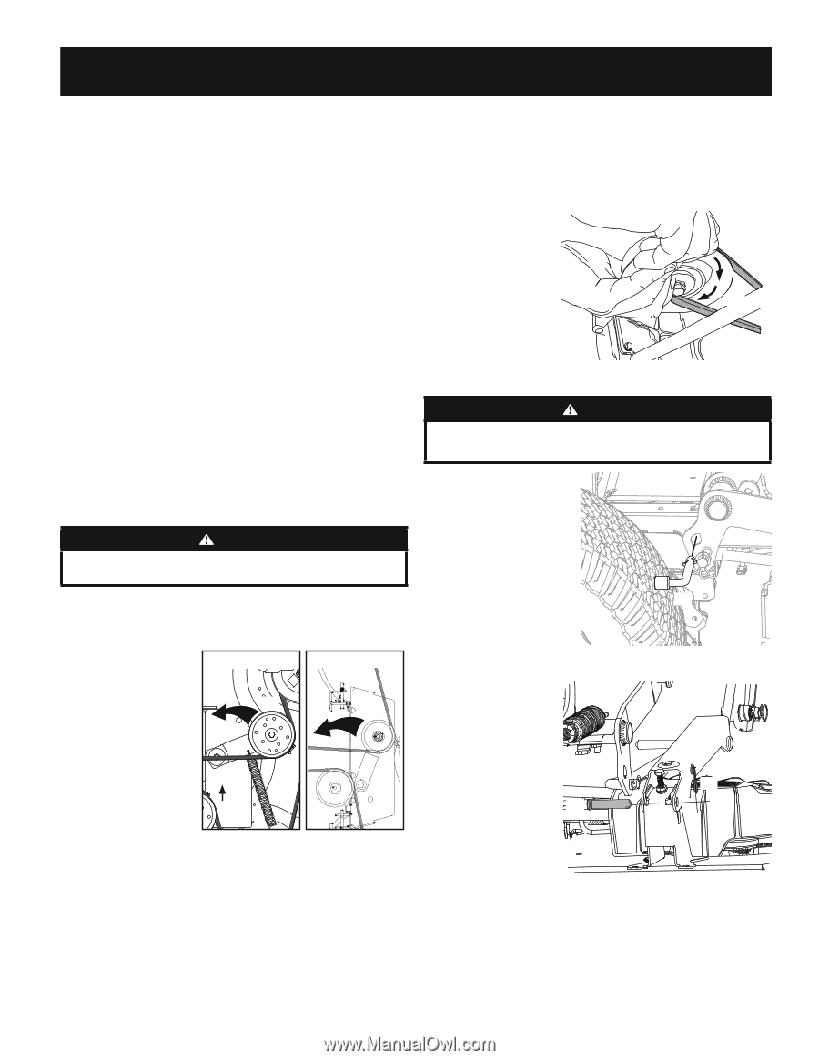
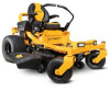
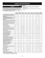
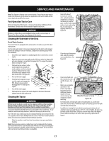
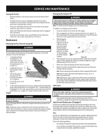
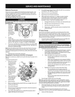
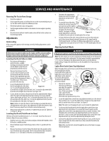
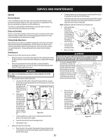
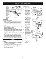
SERVICE AND MAINTENANCE Service Electrical System A fuse is installed to protect the tractor's electrical system from damage caused by excessive amperage. Always use the same capacity fuse for replacement. If the electrical system does not function, check for a blown fuse. If you have a recurring problem with blown fuses, have the tractor's electrical system checked by your authorized service dealer. Relays and Switches There are several safety switches in the electrical system. If a function of the safety interlock system described earlier is not functioning properly, have the electrical system checked by your authorized service dealer. Parking Brake Adjustment If the tractor does not come to a complete stop when the control levers are moved fully outward engaging the parking brake, or if the tractor's rear wheels can roll with the parking brake engaged (and the hydrostatic relief valve open), the brake is in need of adjustment. See your authorized service dealer to have the brake adjusted. Deck Removal Remove the tractor deck from the tractor as follows: 1. Move the tractor to a level surface, disengage the PTO, stop the engine, place the RH and LH drive control levers fully outward into the park brake engaged position. 2. There are two methods for removing the belt, to remove the belt by releasing belt tension go on to step 3, to remove the belt by rolling the belt off the PTO pulley skip ahead to step 4. WARNING Use caution to avoid pinching your fingers when rolling the belt off the PTO pulley. 3. Releasing belt tension with the idler pulley: a. Using the deck lift handle or the deck lift pedal and knob, raise the deck to the position that provides the most horizontal run of the belt between the deck idler pulleys and the PTO pulley on 42" Decks 46/50/54/60" Decks the bottom of the engine. (b) b. Working from (b) the middle of (a) the tractor, pivot the idler bracket (a) and movable idler pulley (b) (a) rearward just far enough to lift the belt up and over the spindle pulley. See Figure 38. Figure 38 c. From beneath the rear of the tractor, slide the belt off of the PTO pulley on the bottom of the engine. d. Lower the deck into the lowest mowing position. e. Skip ahead to step 5. 4. Rolling the belt off the PTO pulley: a. Raise the deck to the position that provides the most horizontal run of the belt between the deck idler pulleys and the PTO pulley on the bottom of the engine. b. Sitting behind the tractor facing forward, reach beneath the tractor to grasp the belt at the front of the PTO pulley. c. Pull the left side of the belt rearward and downward while manually turning the PTO pulley to the right until the belt rides out onto the edge of the lower sheave of the pulley. Note: If pulling the right side of the belt, turn the pulley left. d. While still holding the PTO belt (a) downward, continue turning the PTO pulley (b) until the PTO belt (a) is rolled off the PTO pulley (b). Refer to Figure 39. (a) (b) e. Lower the deck into the lowest mowing position. f. Move on to step 5. (a) Figure 39 WARNING The deck lift on tractors with the deck lift knob is spring-assisted and under tension. Injury can occur if spring-assisted deck lift is released suddenly. Always use the multi-tool to secure the deck lift in place. 5. On tractors equipped with the deck lift knob, use the deck lift pedal and deck lift knob to place the deck in the lowest position and use the multi- tool (a) to lock the deck lift components in place as shown in Figure 40. On tractors with a deck lift handle, lower the deck into the lowest position. (a) a. Remove the two bow-tie pins (a) from the clevis pins (b) that secure the lift link brackets (c) to the rear deck lift brackets (d) on the deck. Remove the clevis pins (b). (b) See Figure 41. Figure 40 (c) (a) (d) Figure 41 21
-
 1
1 -
2
-
3
-
4
-
5
-
6
-
7
-
8
-
9
-
10
-
11
-
12
-
13
-
14
-
15
-
 16
16 -
 17
17 -
 18
18 -
 19
19 -
 20
20 -
 21
21 -
 22
22 -
 23
23 -
 24
24 -
 25
25 -
 26
26 -
27
-
28
-
29
-
30
-
31
-
32
-
33
-
34
-
35
-
36
-
37
-
38
-
39
-
40
-
41
-
42
-
43
-
44
-
45
-
46
-
47
-
48
 |
 |