Cuisinart CSB-55 CSB-55N Manual - Page 8
Plastic Blade Sheath, Blade Ring, Prep Bowl, Blade
 |
UPC - 086279106438
View all Cuisinart CSB-55 manuals
Add to My Manuals
Save this manual to your list of manuals |
Page 8 highlights
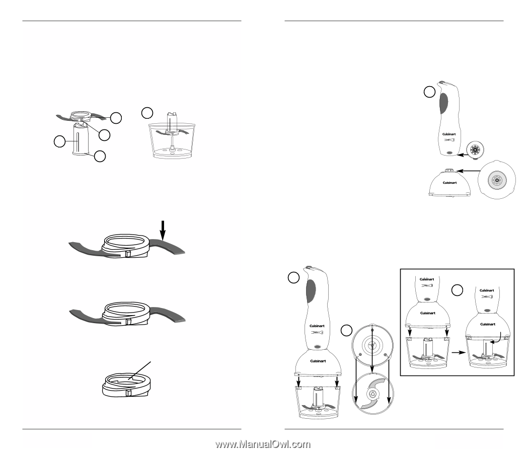
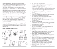
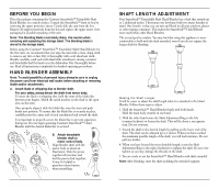
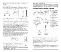
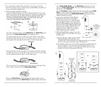
2. The metal blade assembly shaft is attached to the bottom of the Prep Bowl. If not already in place, slide the fully assembled Blade Assembly over the top of the blade assembly shaft. 2a. Putting together the Blade Assembly: Connect the Blade Ring (F) to the Plastic Blade Sheath (G). Line up the blade ring opening with the plastic sheath. Let the blade ring slide to the bottom of the plastic sheath. HOLD THE BLADE RING BY THE CENTRAL HUB HOLDING RIBS (grips)(K) ONLY. DO NOT TOUCH THE RAZOR SHARP BLADES. 2a F K N G Note these important features of the Blade Ring. The Blade Ring can be placed over the Plastic Blade Sheath in two different ways: If you hold it this way (A), you will see the word "Sharp" on the blade. Assemble the blade this side up to use the sharp edge. (see the section on processing food for information about when to use the sharp edge.) A. SHARP SIDE If you hold it this way (B), you will see no writing on the blade. Assemble the blade this side up to use the blunt edge. (See the section on processing food for information about when to use the blunt edge.) B. BLUNT SIDE UP There are notches (C) on opposite sides of the interior of the hub. These fit over ridges on the sides of the Plastic Blade Sheath. C. Notch Pick up the Blade Ring by its hub holding ribs (grips) and line up the notches in the interior of the Blade Ring hub with the ridges on the sides 14 of the Plastic Blade Sheath. Let the Blade Ring slide down to the bottom of the Plastic Blade Sheath. The lower blade should almost touch the bottom of the Prep Bowl. Lift the Prep Bowl, holding it firmly from the bottom. Pick up the Blade Ring by its hub holding ribs (grips) and turn it very slightly clockwise. This locks it in place on the Plastic Blade Sheath and prevents it from sliding up during processing. 3. Connect the SmartStick™ Hand Blender 3 Motor Body to the top of the Chopper Grinder Attachment Cover. Align the spline in the Chopper Grinder Cover's drive shaft with the ribbed opening on the underside of the motor body. When aligned properly, slide the two pieces together until they mate. You will feel and hear a slight click. It may be ® SmartStickTM EXTENDABLE SHAFT helpful to press the rubber release button when sliding these pieces together. PRESS BUTTON TO DETACH Motor Body Bottom and Chopper Grinder Cover Top View 4. With the Hand Blender in place, locate the Chopper Grinder cover and place it on top of the prep bowl. ® SmartStick™ MINI PREP® Chopper Grinder Attachment 4a. Be sure that the 3 ridges at the top of the Blade Assembly line up with the 3-arm propeller gear in the underside of the chopper grinder cover, and that the cover is seated all around the top of the prep bowl. 4b.To properly seat the cover you must line up the three molded pins from the cover with the 3 slots at the top of the Prep Bowl. Rotate cover counterclockwise to secure it to the prep bowl. Rotate the cover until the pins are in the far left position in the slots. 4 ® SmartStickTM EXTENDABLE SHAFT PRESS BUTTON TO DETACH ® SmartStick™ MINI PREP® Chopper Grinder Attachment Inside View of Chopper Grinder Cover 4a ® SmartStickTM EXTENDABLE SHAFT PRESS BUTTON TO DETACH ® SmartStick™ MINI PREP® Chopper Grinder Attachment 4b ® SmartStickTM EXTENDABLE SHAFT PRESS BUTTON TO DETACH ® SmartStick™ MINI PREP® Chopper Grinder Attachment Inside View of Prep Bowl 15
-
 1
1 -
2
-
 3
3 -
 4
4 -
 5
5 -
 6
6 -
 7
7 -
 8
8 -
 9
9 -
 10
10 -
 11
11 -
 12
12 -
 13
13 -
14
-
15
 |
 |