CyberPower CP1350AVRLCD User Manual - Page 7
Definitions For Illuminated Lcd Indicators
 |
View all CyberPower CP1350AVRLCD manuals
Add to My Manuals
Save this manual to your list of manuals |
Page 7 highlights
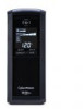
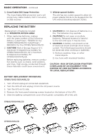
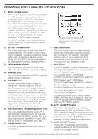
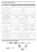
DEFINITIONS FOR ILLUMINATED LCD INDICATORS 1. INPUT voltage meter: This meter measures the AC voltage that the UPS system is receiving from the utility wall outlet. The UPS is designed, through the use of automatic voltage regulation, to continuously correct output voltage to connected equipment to a safe 120 voltage output range. In the event of a complete power loss, sustained under-voltage, or over-voltage, the UPS relies on its internal battery to supply consistent 110/120 output voltage. The INPUT voltage meter can be used as a diagnostic tool to identify poor-quality input power. 2. OUTPUT voltage meter: This meter measures, in real time, the AC voltage that the UPS system is providing to the computer, such as normal line mode, AVR mode, and battery backup mode. (Note: The OUTPUT voltage meter shows the status of the battery backup outlets.) 3. ESTIMATED RUN TIME: This displays the run time estimate of the UPS with current battery capacity and load. 4. NORMAL icon: This icon appears when the UPS is working under normal conditions. 5. BATTERY icon: During a sustained under-voltage or power loss, this icon appears and an alarm sounds (two short beeps followed by a pause) to indicate the UPS is operating from its internal batteries. During a sustained under-voltage or power loss, the alarm will sound continuously to indicate the UPS's batteries are nearly out of power. You should save files and turn off your equipment immediately or allow the software to shut the system down. 6. AVR (Automatic Voltage Regulation) icon: This icon appears whenever your UPS is automatically correcting low AC line voltage without using battery power. This is a normal, automatic operation of your UPS, and no action is required on your part. 7. SILENT MODE icon: This icon appears whenever the UPS is in silent mode. The LCD screen indicates a variety of UPS operational conditions. All descriptions apply when the UPS is plugged into an AC outlet and turned on or when the UPS is on battery. 8. OVER LOAD icon: This icon appears and an alarm sounds to indicate the battery-supplied outlets are overloaded. To clear the overload, unplug some of your equipment from the battery-supplied outlets until the icon turns off and the alarm stops. 9. FAULT icon: This icon appears if there is a problem with the UPS. Contact CyberPower Systems for further help and support. E01: Charger Fault - Overcharge (Contact CyberPower Systems for support.) E02: Charger Fault - No Charge (Contact CyberPower Systems for support.) E11: Battery Overvoltage (Contact CyberPower Systems for support.) E21: Battery Output Short Fault (Turn on the UPS again.) E22: Battery Mode or AC/Utility Power Mode Overload Fault (Unplug at least one piece of equipment from battery outlets and turn the UPS on again.) 10. BATT. CAPACITY meter: This meter displays the approximate charge level (in 20% increments) of the UPS's internal battery. During a power loss or sustained low-voltage, the UPS switches to battery power, the BATTERY icon appears, and the charge level decreases. 11. LOAD CAPACITY meter: This meter displays the approximate output load level (in 20% increments) of the UPS battery outlets. For more information about functions setup, please refer to the Function Setup Guide.
-
 1
1 -
 2
2 -
 3
3 -
 4
4 -
 5
5 -
 6
6 -
 7
7 -
 8
8 -
 9
9 -
 10
10
 |
 |