CyberPower PR2200ELCDRTXL2U User Manual - Page 6
BASIC OPERATION continued
 |
View all CyberPower PR2200ELCDRTXL2U manuals
Add to My Manuals
Save this manual to your list of manuals |
Page 6 highlights
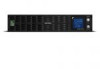
BASIC OPERATION (continued) 5. Battery Backup, Surge Protected and AVR protected Outlets This unit provides a total of ten outlets with battery backup and surge protection. They ensure that connected equipment will keep an uninterrupted operation over a period of time, during a power failure. Critical /Non-critical It is possible to program the unit in a way so that the outlet block marked as "non-Critical", (6 ports), will stop the provision of power to connected equipment after a certain period of time, thus making more runtime available for the equipment connected on the outlets marked as "Critical", (4 ports). In other words, the user can establish runtime priority for certain connected equipment, maximizing its "availability" during a prolonged power outage. This type of control takes place with the use of the provided PowerPanel® Business Edition S/W. 6. AC Inlet Connect the AC Power cord to a properly wired and grounded outlet. 7. Output Circuit Breaker The circuit breaker serves to provide output overload and fault protection. 8. Input Circuit Breaker The circuit breaker serves to provide input overload and fault protection. 9. USB port to PC This is a connectivity port allowing communication and control among the UPS and the connected computer. You should install on your computer the PowerPanel® Business Edition software appropriate to the operating system you are using. 10. Surge Protected Communication Ports - RJ11/RJ45 These ports are being used to protect from various surge-conditions the standard RJ-45/RJ-11 based, (ADSL, LAN, Phone/Modem-Lines), cabling systems. 11. Serial Port I (Primary) Serial port I allow for bi-directional communication among the UPS and the computer. The UPS can control the computer's shutdown in case of an emergency, and at the same time, the computer can monitor the UPS and alter its various programmable parameters. 12. Serial Port II (Secondary) Serial Port II allows the UPS to initiate the connected computer's graceful auto-shutdown in case of an emergency. 13. SNMP/HTTP Network slot Remove the cover panel to install optional SNMP, allowing your UPS be controlled and monitored via a network connection. 14. EPO (Emergency Power Off) Port Allow for an emergency UPS Power-Off from a remote location. 15. External Battery Pack Connector Provides a connection for additional CyberPower external battery packs for extended runtime. 6 Copyright © 2016 CyberPower Systems, Inc.
-
 1
1 -
 2
2 -
 3
3 -
 4
4 -
 5
5 -
 6
6 -
 7
7 -
 8
8 -
 9
9 -
 10
10 -
 11
11 -
 12
12 -
13
 |
 |
