D-Link DES-3028 Product Manual - Page 103
Asymmetric VLANs, Asymmetric VLANs Example
 |
UPC - 790069305375
View all D-Link DES-3028 manuals
Add to My Manuals
Save this manual to your list of manuals |
Page 103 highlights
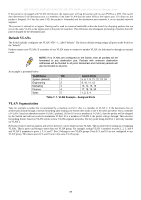
DES-3028 DES-3028P DES-3028G DES-3052 DES-3052P Layer 2 Fast Ethernet Managed Switch Asymmetric VLANs The DES-3028 Switch Series has the capability to create and utilize Asymmetric VLANs on the Switch. Asymmetric VLANs allow devices to transmit packets on one VLAN and receive it on another VLAN. This configuration is accomplished through the use of three functions: enabling Asymmetric VLANs, VLAN creation, and GVRP configuration. Consider the example below. Figure 7- 4. Asymmetric VLANs Example In order to accomplish an Asymmetric VLAN configuration, the user must do a three part configuration: 1. Enable Asymmetric VLANs using the Advanced Settings window located in the Configuration folder. Overlapping VLANs cannot be configured unless this function is enabled. 2. Configure the VLAN settings. The example above uses ports 1-8 to hold the devices to be shared on the network, such as shared servers and shared printers. Therefore, this group of ports is to be included for all VLANs. VLAN V2 is then configured to include ports 1-8 (shared VLAN ports) and the set of ports to be separated from the other subsetted VLANs (ports 9-16). VLAN V3 is then configured to include ports 1-8 (shared ports) and the set of ports to be separated from the other subsetted VLANs (17-24). Therefore we have two VLANs who both share ports and have ports that are separated from each other and thus cannot communicate with each other. 3. Configure the PVID settings for the Switch through the GVRP function located in the VLANs folder. The user is to set the shared set of ports as PVID 1, the other separated groups of ports as PVID 2 and PVID 3. After completing the previous configuration, the user is now able to share the network resources set on the shared group of ports (nominated as PVID 1), with both smaller subsets of VLANs (nominated PVID 2 and PVID 3). Yet, VLAN V1 and VLAN V2 are incapable of sharing information with each other and the Overlapping VLAN configuration has been successfully created. 89
-
 1
1 -
2
-
3
-
4
-
5
-
6
-
7
-
8
-
9
-
10
-
11
-
12
-
13
-
14
-
15
-
16
-
17
-
18
-
19
-
20
-
21
-
22
-
23
-
24
-
25
-
26
-
27
-
28
-
29
-
30
-
31
-
32
-
33
-
34
-
35
-
36
-
37
-
38
-
39
-
40
-
41
-
42
-
43
-
44
-
45
-
46
-
47
-
48
-
49
-
50
-
51
-
52
-
53
-
54
-
55
-
56
-
57
-
58
-
59
-
60
-
61
-
62
-
63
-
64
-
65
-
66
-
67
-
68
-
69
-
70
-
71
-
72
-
73
-
74
-
75
-
76
-
77
-
78
-
79
-
80
-
81
-
82
-
83
-
84
-
85
-
86
-
87
-
88
-
89
-
90
-
91
-
92
-
93
-
94
-
95
-
96
-
97
-
 98
98 -
 99
99 -
 100
100 -
 101
101 -
 102
102 -
 103
103 -
 104
104 -
 105
105 -
 106
106 -
 107
107 -
 108
108 -
109
-
110
-
111
-
112
-
113
-
114
-
115
-
116
-
117
-
118
-
119
-
120
-
121
-
122
-
123
-
124
-
125
-
126
-
127
-
128
-
129
-
130
-
131
-
132
-
133
-
134
-
135
-
136
-
137
-
138
-
139
-
140
-
141
-
142
-
143
-
144
-
145
-
146
-
147
-
148
-
149
-
150
-
151
-
152
-
153
-
154
-
155
-
156
-
157
-
158
-
159
-
160
-
161
-
162
-
163
-
164
-
165
-
166
-
167
-
168
-
169
-
170
-
171
-
172
-
173
-
174
-
175
-
176
-
177
-
178
-
179
-
180
-
181
-
182
-
183
-
184
-
185
-
186
-
187
-
188
-
189
-
190
-
191
-
192
-
193
-
194
-
195
-
196
-
197
-
198
-
199
-
200
-
201
-
202
-
203
-
204
-
205
-
206
-
207
-
208
-
209
-
210
-
211
-
212
-
213
-
214
-
215
-
216
-
217
-
218
-
219
-
220
-
221
-
222
-
223
-
224
-
225
-
226
-
227
-
228
-
229
-
230
-
231
-
232
-
233
-
234
-
235
-
236
-
237
-
238
-
239
-
240
-
241
-
242
-
243
-
244
-
245
-
246
-
247
-
248
-
249
-
250
-
251
-
252
-
253
-
254
-
255
-
256
-
257
-
258
-
259
-
260
-
261
-
262
-
263
-
264
-
265
-
266
-
267
-
268
-
269
-
270
-
271
-
272
-
273
-
274
-
275
-
276
-
277
-
278
-
279
-
280
-
281
-
282
-
283
-
284
-
285
-
286
-
287
-
288
-
289
-
290
-
291
-
292
-
293
-
294
-
295
-
296
-
297
-
298
-
299
-
300
-
301
-
302
-
303
-
304
-
305
-
306
-
307
-
308
-
309
-
310
-
311
-
312
-
313
-
314
-
315
-
316
-
317
-
318
-
319
-
320
-
321
-
322
-
323
-
324
-
325
-
326
-
327
-
328
-
329
-
330
-
331
-
332
-
333
 |
 |
