D-Link DFE-550FX User Guide - Page 12
Connecting the Network Cable, conflicting Interrupt Number to the DFE-550FX.
 |
UPC - 790069226649
View all D-Link DFE-550FX manuals
Add to My Manuals
Save this manual to your list of manuals |
Page 12 highlights
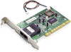
D-Link DFE-550FX Adapter available PCI Bus expansion slot. 4. Install the bracket screw to secure the card to the computer chassis. 5. Replace the computer cover. 6. Reconnect the computer power cord, and switch the computer power on. If the BIOS section of your computer boot program is Plug and Play compliant, then at power-up the BIOS will automatically configure itself for the newly installed DFE550FX adapter. NOTE: Due to a fault in some Plug-n-Play BIOS programs, it happens occasionally that a newly installed adapter is assigned an IRQ Number which is already assigned to another device. In such a case, the conflicting IRQ Numbers (IRQ numbers must be unique) will cause faults in the behavior of both devices. If this happens, it is necessary to run the CMOS Setup utility, and manually assign a nonconflicting Interrupt Number to the DFE-550FX. Connecting the Network Cable Multimode (62.5/125µm or 50/125µm) fiber cabling with an IEEE recommended SC connector is required for the adapter. Observe the correct relationship between the receive (Rx) and transmit (Tx) ports on the adapter and repeater. If there is a need to monitor the adapter's faceplate LEDs, make the rear of the PC or workstation accessible and leave sufficient clearance for cabling and service. The maximum length of fiber cable between any station and its supporting hub is 2,000 meters at full-duplex and 412 meters at half-duplex. 5
-
 1
1 -
2
-
3
-
4
-
5
-
6
-
 7
7 -
 8
8 -
 9
9 -
 10
10 -
 11
11 -
 12
12 -
 13
13 -
 14
14 -
 15
15 -
 16
16 -
 17
17 -
18
-
19
-
20
-
21
-
22
-
23
 |
 |
