D-Link DGS-1210-10P Product Manual - Page 33
System > Trap Settings For SmartConsole, System > Port Settings, Fiber Port Link Up/Link Down - poe
 |
UPC - 790069329388
View all D-Link DGS-1210-10P manuals
Add to My Manuals
Save this manual to your list of manuals |
Page 33 highlights
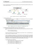
5 Configuration D-Link Web Smart Switch User Manual System > Trap Settings For SmartConsole By configuring the Trap Setting, it allows SmartConsole Utility to monitor specified events on this Web-Smart Switch. By default, Trap Setting is disabled. When the Trap Setting is enabled, enter the Destination IP address of the managing station that will receive trap information. Figure 42 - System > Trap Setting You can select which event message(s) will be sent to the managing station System Event: The system level messages, which contains: Device Bootup - System boot-up information. Illegal Login - Events of incorrect password logins, recording the IP of the originating PC. Fiber Port Link Up/Link Down: Fiber port connection information. Twisted pair Port Link Up/Link Down: Copper port connection information. RSTP Port State Change: Events of a RSTP port state changes. Firmware Upgrade State: Information of firmware upgrade success or failure. PoE Power On / Off Event: PoE port powering information. PoE Power Error Event: Information about PoE powering error. PoE over max power budget Event: over max system power budget information. System > Port Settings In the Port Setting page, the status of all ports can be monitored and adjusted for optimum configuration. By selecting a range of ports (From Port and To Port), the Speed can be set for all selected ports by clicking Apply. Press the Refresh button to view the latest information. Figure 43 - System > Port Setting Speed: Gigabit Fiber connections can operate in 1000M Full Force Mode, Auto Mode or Disabled. Copper connections can operate in Forced Mode settings (1000M Full, 100M Full, 100M Half, 10M Full, 10M Half), Auto, or Disabled. 100M Fiber connections support 100M Full Force Mode, 100M Half Force Mode, or Disabled. The default setting for all ports is Auto. NOTE: Be sure to adjust port speed settings appropriately after changing the connected cable 27
-
 1
1 -
2
-
3
-
4
-
5
-
6
-
7
-
8
-
9
-
10
-
11
-
12
-
13
-
14
-
15
-
16
-
17
-
18
-
19
-
20
-
21
-
22
-
23
-
24
-
25
-
26
-
27
-
 28
28 -
 29
29 -
 30
30 -
 31
31 -
 32
32 -
 33
33 -
 34
34 -
 35
35 -
 36
36 -
 37
37 -
 38
38 -
39
-
40
-
41
-
42
-
43
-
44
-
45
-
46
-
47
-
48
-
49
-
50
-
51
-
52
-
53
-
54
-
55
-
56
-
57
-
58
-
59
-
60
-
61
-
62
-
63
-
64
-
65
-
66
-
67
-
68
-
69
-
70
-
71
-
72
-
73
 |
 |
