D-Link DGS-1210-10P Product Manual - Page 9
DGS-1210-10P, Front Panel, Rear Panel - d link manual
 |
UPC - 790069329388
View all D-Link DGS-1210-10P manuals
Add to My Manuals
Save this manual to your list of manuals |
Page 9 highlights
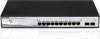
1 Product Introduction D-Link Web Smart Switch User Manual the switches with other third-party devices for management in an SNMP-enabled environment. D-Link Web Smart Switches also come with the D-View plug-in module that works with D-View 6 SNMP Management Software, and provides easy-to-use graphic interface and facilitates the operation efficiency. DGS-1210-10P 8-Port 10/100/1000Mbps plus 2 1000Base-T/SFP ports Web Smart PoE Switch Front Panel Figure 1 - DGS-1210-10P Front Panel SFP ports for optical transceivers Power LED : The Power LED lights up when the Switch is connected to a power source. Pwr Max: The Pwr Max LED lights up when the Switch reaches the maximum power budget defined by the administrator via PoE System Settings page of Web GUI or the default power budget of 78 Watts. Reset: By pressing the Reset button, the Switch will change back to the default configuration and all changes will be lost. Mode: By pressing the Mode button, the Port LED will switch between Link/Act and PoE modes. Port Link/Act/Speed LED (1-8, 9T, 10T, 9F, 10F): When mode LED lights up in Link/Act mode, the port LEDs indicate a network link through the corresponding port. Blinking indicates the Switch is either sending or receiving data to the port. When the port LED glows in amber, it indicates the port is running on 10M or 100M. When the port LED glows in green, it is running on 1000Mbps. NOTE: On DGS-1210-10P, the SFP ports are shared with normal RJ-45 ports 9 to 10. When optical transceiver is inserted to SFP port and link up, the RJ-45 port cannot be used. Port PoE LED (1-8): When mode LED lights up in PoE mode, the port LEDs indicate powering status over the corresponding port. Rear Panel Figure 2 - DGS-1210-10P Rear Panel Power: The power port is where to connect the AC power cord. 3
-
 1
1 -
2
-
3
-
 4
4 -
 5
5 -
 6
6 -
 7
7 -
 8
8 -
 9
9 -
 10
10 -
 11
11 -
 12
12 -
 13
13 -
 14
14 -
15
-
16
-
17
-
18
-
19
-
20
-
21
-
22
-
23
-
24
-
25
-
26
-
27
-
28
-
29
-
30
-
31
-
32
-
33
-
34
-
35
-
36
-
37
-
38
-
39
-
40
-
41
-
42
-
43
-
44
-
45
-
46
-
47
-
48
-
49
-
50
-
51
-
52
-
53
-
54
-
55
-
56
-
57
-
58
-
59
-
60
-
61
-
62
-
63
-
64
-
65
-
66
-
67
-
68
-
69
-
70
-
71
-
72
-
73
 |
 |
