D-Link DGS-1210-24 Product Manual - Page 34
Link Status, System > SNMP Settings, Enabled, Apply, Community Setting, Read_Only, public - 48 default password
 |
UPC - 790069332296
View all D-Link DGS-1210-24 manuals
Add to My Manuals
Save this manual to your list of manuals |
Page 34 highlights
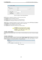
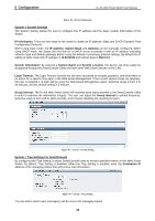
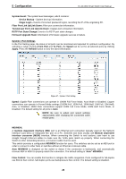
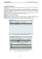
5 Configuration D-Link Web Smart Switch User Manual Link Status: Reporting Down indicates the port is disconnected. System > SNMP Settings Simple Network Management Protocol (SNMP) is an OSI Layer 7 (Application Layer) protocol designed specifically for managing and monitoring network devices. SNMP enables network management stations to read and modify the settings of gateways, routers, switches, and other network devices. Use SNMP to configure system features for proper operation, monitor performance and detect potential problems in the Switch or LAN. Managed devices that support SNMP include software (referred to as an agent), which runs locally on the device. A defined set of variables (managed objects) is maintained by the SNMP agent and used to manage the device. These objects are defined in a Management Information Base (MIB), which provides a standard presentation of the information controlled by the on-board SNMP agent. SNMP defines both the format of the MIB specifications and the protocol used to access this information over the network. The default SNMP setting is disabled. Click Enabled to set Community Settings and then Apply. Figure 48 - System > SNMP Setting Community Setting: In support of SNMP version 1, the Web-Smart Switch accomplishes user authentication by using Community Settings that function as passwords. The remote user SNMP application and the Switch SNMP must use the same community string. SNMP packets from a station that are not authenticated are ignored (dropped). The default community strings for the Switch used for SNMP v.1 management access are: Read_Only: The community with read-only privilege allows authorized management stations to retrieve MIB objects. The default name is public. Read_Write: The community with read/write privilege allows authorized management stations to retrieve and modify MIB objects. The default name is private. Trap Setting: Traps are messages that alert network personnel of events that occur on the Switch. Such events can be as severe as a reboot (someone accidentally turned the Switch OFF), or less serious events such as a port status change. The Switch can generate traps and send them to the trap recipient (i.e. network administrator). Setting up a Trap: Select Enable, enter a Trap Name, add the IP of the device to be monitored, and select the event(s) to trap. The available trap Events to choose from include: SNMP Authentication Traps System Device Bootup Fiber Link Up / Link Down Twisted Pair Link Up / Link Down RSTP Port State Change Firmware Upgrade State 30
-
 1
1 -
2
-
3
-
4
-
5
-
6
-
7
-
8
-
9
-
10
-
11
-
12
-
13
-
14
-
15
-
16
-
17
-
18
-
19
-
20
-
21
-
22
-
23
-
24
-
25
-
26
-
27
-
28
-
 29
29 -
 30
30 -
 31
31 -
 32
32 -
 33
33 -
 34
34 -
 35
35 -
 36
36 -
 37
37 -
 38
38 -
 39
39 -
40
-
41
-
42
-
43
-
44
-
45
-
46
-
47
-
48
-
49
-
50
-
51
-
52
-
53
-
54
-
55
-
56
-
57
-
58
-
59
-
60
-
61
-
62
-
63
-
64
-
65
-
66
-
67
-
68
-
69
-
70
-
71
 |
 |