D-Link DGS-1210-24 Product Manual - Page 7
DGS-1210-16, Port Link/Act/Speed LED 1-20, 21F, 22F, 23F, 24F, 21T, 22T, 23T, 24T - d link manual
 |
UPC - 790069332296
View all D-Link DGS-1210-24 manuals
Add to My Manuals
Save this manual to your list of manuals |
Page 7 highlights
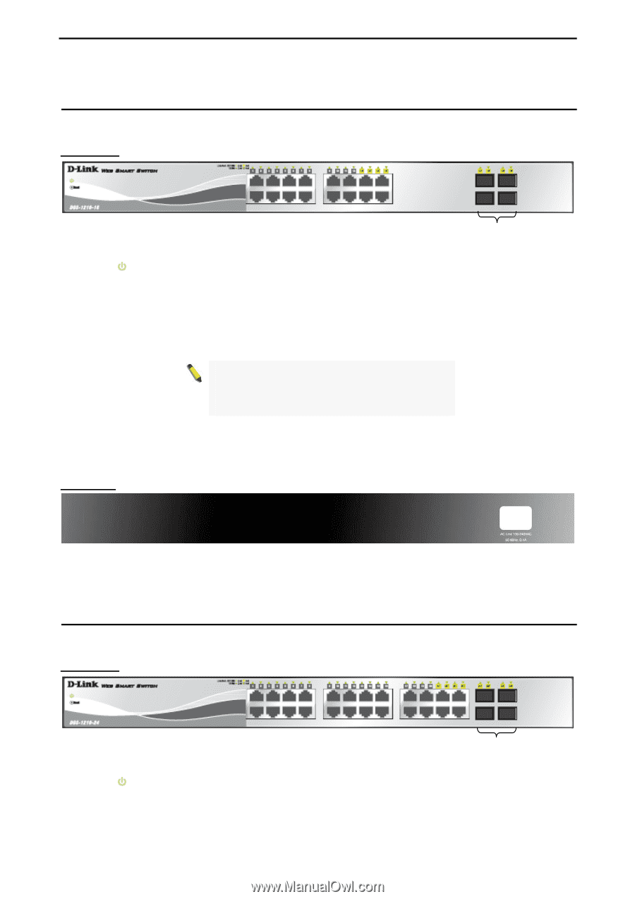
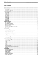
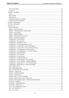
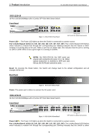
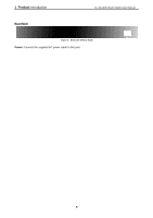
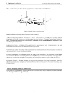
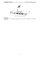
1 Product Introduction D-Link Web Smart Switch User Manual DGS-1210-16 16-Port 10/100/1000Mbps with 4 Combo SFP Slot Web Smart Switch Front Panel Figure 1 - DGS-1210-16 Front Panel SFP ports for optical transceivers Power LED : The Power LED lights up when the Switch is connected to a power source. Port Link/Act/Speed LED (1-12, 13F, 14F, 15F, 16F, 13T, 14T, 15T, 16T): The Link/Act/Speed LED flashes, which indicates a network link through the corresponding port. Blinking indicates that the Switch is either sending or receiving data to the port. When a port has an amber light, this indicates that the port is running on 10M or 100M. When it has a green light it is running on 1000M. NOTE: On DGS-1210-16, the SFP ports are shared with normal RJ-45 ports 13 to 16. When optical transceiver is inserted to SFP port and link up, the RJ-45 port cannot be used. Reset: By pressing the Reset button, the Switch will change back to the default configuration and all changes will be lost. Rear Panel Figure 2 - DGS-1210-16 Rear Panel Power: The power port is where to connect the AC power cord. DGS-1210-24 24-Port 10/100/1000Mbps with 4 Combo SFP Slot Web Smart Switch Front Panel Figure 3 - DGS-1210-24 Front Panel SFP ports for optical transceivers Power LED : The Power LED lights up when the Switch is connected to a power source. Port Link/Act/Speed LED (1-20, 21F, 22F, 23F, 24F, 21T, 22T, 23T, 24T): The Link/Act/Speed LED flashes, which indicates a network link through the corresponding port. Blinking indicates that the Switch is either 3
-
 1
1 -
 2
2 -
 3
3 -
 4
4 -
 5
5 -
 6
6 -
 7
7 -
 8
8 -
 9
9 -
 10
10 -
 11
11 -
 12
12 -
13
-
14
-
15
-
16
-
17
-
18
-
19
-
20
-
21
-
22
-
23
-
24
-
25
-
26
-
27
-
28
-
29
-
30
-
31
-
32
-
33
-
34
-
35
-
36
-
37
-
38
-
39
-
40
-
41
-
42
-
43
-
44
-
45
-
46
-
47
-
48
-
49
-
50
-
51
-
52
-
53
-
54
-
55
-
56
-
57
-
58
-
59
-
60
-
61
-
62
-
63
-
64
-
65
-
66
-
67
-
68
-
69
-
70
-
71
 |
 |