D-Link DGS-1210-48 Product Manual
D-Link DGS-1210-48 Manual
 |
UPC - 790069332371
View all D-Link DGS-1210-48 manuals
Add to My Manuals
Save this manual to your list of manuals |
D-Link DGS-1210-48 manual content summary:
- D-Link DGS-1210-48 | Product Manual - Page 1
- D-Link DGS-1210-48 | Product Manual - Page 2
D-Link Web Smart Switch User Manual Table of Contents Table of Contents ...i About This Guide...1 Terms/Usage...1 Copyright and Trademarks ...1 Product Introduction ...2 DGS-1210-16 ...3 Front Panel ...3 Rear Panel...3 DGS-1210-24 ...3 Front Panel ...3 Rear Panel...4 DGS-1210-48 ...4 Front - D-Link DGS-1210-48 | Product Manual - Page 3
Table of Contents D-Link Web Smart Switch User Manual Save Configuration ...23 Save Log ...23 Tool Bar > Tool Menu ...23 Reset ...23 Reset System ...23 Reboot Device ...24 Configuration Backup & Restore ...24 Firmware Backup and Upload ...24 Tool Bar > Smart Wizard...25 Tool Bar > Online Help...25 - D-Link DGS-1210-48 | Product Manual - Page 4
Table of Contents D-Link Web Smart Switch User Manual Command Line Interface...59 To connect a switch via TELNET:...59 Logging on to the Command Line Interface 59 CLI Commands: ...59 Download...59 Upload ...60 Config ipif System...60 Logout...60 Ping ...61 Reboot ...61 Reset ...61 Show ipif ...61 - D-Link DGS-1210-48 | Product Manual - Page 5
About This Guide D-Link Web Smart Switch User Manual About This Guide This guide provides instructions to install the D-Link Gigabit Web Smart Switch DGS-1210-16/24/48, how to use the SmartConsole Utility, and to configure Web-based Management step-by-step. Note: The model you have purchased may - D-Link DGS-1210-48 | Product Manual - Page 6
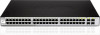
: 16, 24, and 48 Gigabit Ethernet ports. Supporting auto-detection of MDI/MDIX, these switches bring inexpensive and easy Ethernet connection to the desktops. Each switch provides 4 combo SFP slots, which supports both 1000M and 100M fiber connections with appropriate fiber transceivers. D-Link - D-Link DGS-1210-48 | Product Manual - Page 7
the Reset button, the Switch will change back to the default configuration and all changes will be lost. Rear Panel Figure 2 - DGS-1210-16 Rear Panel Power: The power port is where to connect the AC power cord. DGS-1210-24 24-Port 10/100/1000Mbps with 4 Combo SFP Slot Web Smart Switch Front - D-Link DGS-1210-48 | Product Manual - Page 8
link up, the RJ-45 port cannot be used. Rear Panel CAUTION: The MiniGBIC ports should use UL listed optical transceiver product. Figure 4 - DGS-1210-24 Rear Panel Power: Connect the supplied AC power cable to this port. DGS-1210-48 48-Port 10/100/1000Mbps with 4 Combo SFP Slot Web Smart Switch - D-Link DGS-1210-48 | Product Manual - Page 9
1 Product Introduction D-Link Web Smart Switch User Manual Rear Panel Figure 6 - DGS-1210-48 Rear Panel Power: Connect the supplied AC power cable to this port. 5 - D-Link DGS-1210-48 | Product Manual - Page 10
is missing or damaged, please contact your local D-Link reseller for replacement. One D-Link Web-Smart Switch One AC power cord Four rubber feet Screws and two mounting brackets One Multi-lingual Getting Started Guide One CD with User Manual, SmartConsole Utility program, and D-View Module If any - D-Link DGS-1210-48 | Product Manual - Page 11
2 Hardware Installation D-Link Web Smart Switch User Manual Then, use the screws provided with the equipment rack to mount the switch in the rack. Figure 9 - Mount the Switch in the rack or chassis Please be aware of following safety Instructions when installing: A) Elevated Operating Ambient - - D-Link DGS-1210-48 | Product Manual - Page 12
2 Hardware Installation D-Link Web Smart Switch User Manual Figure 10 -Plugging the switch into an outlet Power Failure As a precaution, the switch should be unplugged in case of power failure. When power is resumed, plug the switch back in. 8 - D-Link DGS-1210-48 | Product Manual - Page 13
D-Link Web Smart Switches, the SmartConsole Utility is a more convenient choice. By using the SmartConsole Utility, you do not need to change the IP address of your PC and it is easier to initialize multiple Smart Switches. Please refer to the following installation instructions for the Web-based - D-Link DGS-1210-48 | Product Manual - Page 14
D-Link Web Smart Switch User Manual Login Web-based Management In order to login and configure the switch via an Ethernet connection, the PC must have an IP address in the same subnet as the switch. For example, if the switch has an IP address of 10.90.90.90, the PC should have an IP address of 10 - D-Link DGS-1210-48 | Product Manual - Page 15
3 Getting Started D-Link Web Smart Switch User Manual Option 1: Follow these steps to install the the on-screen instructions to install the utility. 5. Upon completion, go to Start > Programs > D-Link SmartConsole Utility and open the SmartConsole Utility. 6. Connect the Smart Switch to the same - D-Link DGS-1210-48 | Product Manual - Page 16
D-Link Web Smart Switch User Manual 4 SmartConsole Utility The D-Link SmartConsole Utility allows the administrator to quickly discover all D-Link smart switches, which are in the same domain of the PC, collect traps and log messages, and quick access to basic configurations of the switch. The - D-Link DGS-1210-48 | Product Manual - Page 17
4 SmartConsole Utility D-Link Web Smart Switch User Manual Web-Smart Switch will not be discovered. Log Click this icon to launch the Log window. Click View Log to show the events of the SmartConsole Utility and the device. Date/Time indicates when the message was received, IP denotes where it - D-Link DGS-1210-48 | Product Manual - Page 18
Link Web Smart Switch User Manual Figure 18 - SmartConsole File Monitor Save: Records the setting of the Device List as default for the next time the SmartConsole Utility is used. Monitor Save As: Records the setting of the Device List in an appointed filename and file path. Monitor Load: Manually - D-Link DGS-1210-48 | Product Manual - Page 19
D-Link Web Smart Switch User Manual Device Configuration The Device Configuration in the SmartConsole Utility has five icons: Device Settings Device Password Manager Multi Firmware Upgrade DHCP Refresh Web Access and the , , device buttons for the Device List. Device Settings Select a switch - D-Link DGS-1210-48 | Product Manual - Page 20
Utility D-Link Web Smart Switch User Manual Device Password Manager Select a switch from the Device List. Click on this icon to launch the Device Password Manager window. Here you can enter a new password and confirm it. Figure 21 - SmartConsole Device Password Manager Multi Firmware Upgrade - D-Link DGS-1210-48 | Product Manual - Page 21
D-Link Web Smart Switch User Manual Figure 23 - DHCP Refresh Web Access Select a switch from the Device List. Click this icon to launch your Internet browser (eg. The Internet Explorer). Here you can configure the Switch through the Web-based Management utility. You may also get into the Web - D-Link DGS-1210-48 | Product Manual - Page 22
4 SmartConsole Utility D-Link Web Smart Switch User Manual Protocol version: Displays the software version of the Utility. Product Name: Displays the device product name. System Name: Displays the appointed device system name. DHCP: Specify if the device gets the IP address from a DHCP server. - D-Link DGS-1210-48 | Product Manual - Page 23
5 Configuration D-Link Web Smart Switch User Manual 5 Configuration The features and functions of the D-Link Web Smart Switch can be configured for optimum use through the Web-based Management Utility. Smart Wizard Configuration After a successful login, the Smart Wizard will guide you through - D-Link DGS-1210-48 | Product Manual - Page 24
5 Configuration D-Link Web Smart Switch User Manual SNMP Settings The SNMP Setting allows you to quickly enable/disable the SNMP function and configure the SNMP community name. For the complete SNMP function, please check "Setup Menu > System > SNMP Settings" in the Web Interface. The default SNMP - D-Link DGS-1210-48 | Product Manual - Page 25
D-Link Web Smart Switch User Manual System Settings You can manually change the system IP Address, Subnet Mask, and Gateway address by selecting Static and clicking Apply. You can further configure and read more about the above settings in the "Setup Menu > System > System Settings". The default - D-Link DGS-1210-48 | Product Manual - Page 26
5 Configuration D-Link Web Smart Switch User Manual Web-based Management After clicking the Exit button in Smart Wizard you will see the screen below: Tool Bar Function Tree Main Configuration Screen Figure 31 - Web-based Management The above image is the Web-based Management screen. The three - D-Link DGS-1210-48 | Product Manual - Page 27
5 Configuration D-Link Web Smart Switch User Manual Tool Bar > Save Menu The Save Menu provides Save Configuration and Save Log functions. Figure 32 - Save Menu Save Configuration Select to save the entire configuration changes you have made to the device to switch's non-volatile RAM. Figure 33 - D-Link DGS-1210-48 | Product Manual - Page 28
Link Web Smart Switch User Manual Figure 37 - Tool Menu > Reset System Reboot Device Provide a safe way to reboot the system. Click Reboot to restart the switch you to transfer files to a remote TFTP server. Specify TFTP Server IP Address and File Name for the configuration file you want to save to - D-Link DGS-1210-48 | Product Manual - Page 29
5 Configuration D-Link Web Smart Switch User Manual Figure 40 - Tool Menu > Firmware Backup and Upload HTTP: Backup or upgrade the firmware to or from your local PC drive. Click Backup to save the firmware to your disk. Click Browse to browse your inventories for a saved firmware file. Click - D-Link DGS-1210-48 | Product Manual - Page 30
5 Configuration D-Link Web Smart Switch User Manual Figure 42 - User Guide Micro Site 26 - D-Link DGS-1210-48 | Product Manual - Page 31
5 Configuration D-Link Web Smart Switch User Manual Function Tree All configuration options on the switch are accessed through the Setup menu on the left side of the screen. Click on the setup item that you want to configure. The following - D-Link DGS-1210-48 | Product Manual - Page 32
a specific time span in the Web-based Management. If the current session times out (expires), the user is required a re-login before using the Web-based Management again. Selective range is from 3 to 30 minutes, and the default setting is 5 minutes. Group Interval: The D-Link Web Smart Switch will - D-Link DGS-1210-48 | Product Manual - Page 33
5 Configuration D-Link Web Smart Switch User Manual System Event: The system level messages, which contains: Device Bootup - System boot-up information. Illegal Login - Events of incorrect password logins, recording the IP of the originating PC. Fiber Port Link Up/Link Down: Fiber port connection - D-Link DGS-1210-48 | Product Manual - Page 34
network. The default SNMP setting is disabled. Click Enabled to set Community Settings and then Apply. Figure 48 - System > SNMP Setting Community Setting: In support of SNMP version 1, the Web-Smart Switch accomplishes user authentication by using Community Settings that function as passwords. The - D-Link DGS-1210-48 | Product Manual - Page 35
> Jumbo Frame D-Link Gigabit Web Smart Switches support jumbo frames (frames larger than the Ethernet frame size of 1536 bytes) of up to 10,000 bytes (tagged). Default is disabled, Select Enabled then click Apply to turn on the jumbo frame support. 6 Figure 51 - Configuration > Jumbo Frame 31 - D-Link DGS-1210-48 | Product Manual - Page 36
5 Configuration D-Link Web Smart Switch User Manual Configuration > 802.1Q VLAN A VLAN is a group of ports that can be anywhere in the network, but communicate as though they were in the same area. VLANs can be easily organized to reflect department groups (such as R&D, Marketing), usage groups ( - D-Link DGS-1210-48 | Product Manual - Page 37
5 Configuration D-Link Web Smart Switch User Manual Figure 54 - Configuration > 802.1Q VLAN > Example VIDs Figure 55 - Configuration > 802.1Q VLAN > VID Assignments Configuration > Asymmetric VLAN This function is located in the 802.1Q Configuration page. It allows devices in different VLANs to - D-Link DGS-1210-48 | Product Manual - Page 38
5 Configuration D-Link Web Smart Switch User Manual Figure 57 - Configuration > 802.1Q VLAN > Asymmetric VLAN - Enabling Asymmetric VLAN 2. Configure the shared VLAN (VLAN 1) and access VLANs (VLAN 2, 3, 4) In this case, the default VLAN is used as shared VLAN, and the ports that are shared in the - D-Link DGS-1210-48 | Product Manual - Page 39
5 Configuration D-Link Web Smart Switch User Manual After configuration, the user will be able to share the network resources set on the shared group of ports (nominated as PVID 1), with both smaller subsets of VLANs (nominated PVID 2, 3 and 4). However, VLAN 2, 3 and 4 groups are incapable of - D-Link DGS-1210-48 | Product Manual - Page 40
Configuration D-Link Web Smart Switch User Manual Aging Time: Enter a period of time (in hours) to remove a port from the voice VLAN if the port is an automatic VLAN member. When the last voice device stops sending traffic and the MAC address of this voice device is aged out, the voice VLAN aging - D-Link DGS-1210-48 | Product Manual - Page 41
5 Configuration D-Link Web Smart Switch User Manual Select the OUI and press Add to the lower table to complete the Auto Voice VLAN setting. Configuration > Link Aggregation > Port Trunking The Trunking function enables the combining of two or more ports together to increase bandwidth. Up to eight - D-Link DGS-1210-48 | Product Manual - Page 42
5 Configuration D-Link Web Smart Switch User Manual Port Priority (0-65535): Displays the LACP priority value for the port. Default is 128. Activity: There are two different roles of LACP ports: Active - Active LACP ports are capable of processing and sending LACP control frames. This allows LACP - D-Link DGS-1210-48 | Product Manual - Page 43
5 Configuration D-Link Web Smart Switch User Manual Last Member Query Interval (1-25 sec): The Last Member Query Interval is the Max Response Time inserted into Group-Specific Queries sent in response to Leave Group messages, and is also the amount of time between Group-Specific Query messages. - D-Link DGS-1210-48 | Product Manual - Page 44
D-Link Web Smart Switch User Manual extended product life and lower operating costs. By default, the Power Saving mode is enabled. Click Apply specific port while Spanning Tree Protocol (STP) is not enabled in the network, especially when the down links are hubs or unmanaged switches. The Switch - D-Link DGS-1210-48 | Product Manual - Page 45
D-Link Web Smart Switch User Manual Figure 70 - Configuration > Loopback Detection Loopback Detection State: Use the drop-down menu to enable or disable loopback detection. The default is Disabled. Interval (1-32767): Set a Loop detection Interval between 1 and 32767 seconds. The default is - D-Link DGS-1210-48 | Product Manual - Page 46
5 Configuration D-Link Web Smart Switch User Manual Current Time: Displays the current date and time for the switch. If choosing SNTP for the clock source, then the following parameters will be available: SNTP First Server: Specify the IP address of the primary SNTP server from which the system - D-Link DGS-1210-48 | Product Manual - Page 47
Link Web Smart Switch User Manual lower the value, the higher the priority. The default is 32768. TX Hold Count (1-10): Used to set the maximum number of Hello aid in determining that the Switch has spanning tree configuration values consistent with other devices on the bridged LAN. If the value ages - D-Link DGS-1210-48 | Product Manual - Page 48
Link Web Smart Switch User Manual Configuration > Spanning Tree > STP Port Settings STP can be set up on a port per port basis. In addition to setting Spanning Tree parameters for use on the switch level, the Switch be set automatically or as a metric value. The default value is 0 (auto). 0 (auto) - - D-Link DGS-1210-48 | Product Manual - Page 49
5 Configuration D-Link Web Smart Switch User Manual port status. Selecting the False parameter indicates If set to True, it stops the port from propagating received TCN and to other ports. The default value is False. Click Apply for the settings to take effect. Click Refresh to renew the page. - D-Link DGS-1210-48 | Product Manual - Page 50
5 Configuration D-Link Web Smart Switch User Manual Figure 76 - QoS > Bandwidth Control From Port / To Port: Quality of Service priority levels of each port, higher priority means the traffic from this port will be first handled by the switch. For packets that are untagged, the switch will assign - D-Link DGS-1210-48 | Product Manual - Page 51
Default Priority By selecting the DSCP priority, the web pages will changes as seen below: Figure 78 - QoS > DSCP Priority Settings Select QoS Mode: D-Link Smart Switch allows the user to prioritize the traffic based on the 802.1p priority in the VLAN tag or the DSCP (Differentiated Services Code - D-Link DGS-1210-48 | Product Manual - Page 52
5 Configuration D-Link Web Smart Switch User Manual Security > Trusted Host Use Trusted Host function to manage the switch from a remote station. You can enter up to ten designated management stations networks by defining the IP address/Subnet Mask as seen in the figure below. Figure 79 Security - D-Link DGS-1210-48 | Product Manual - Page 53
Link Web Smart Switch User Manual Figure 81 - Security > Port Security Security > 802.1X > 802.1X Settings Network switches 802.1X Setting By default, 802.1X is IP: The IP address of the external Radius Server. You need to specify an RADIUS server to enable 802.1X authentication. Key: Masked password - D-Link DGS-1210-48 | Product Manual - Page 54
5 Configuration D-Link Web Smart Switch User Manual TxPeriod (1 - 65535 sec): This sets the TxPeriod of time for the authenticator PAE state machine. This value determines the period of an EAP Request/Identity packet transmitted to the client. Default is 24 seconds. ReAuthEnabled: This function is - D-Link DGS-1210-48 | Product Manual - Page 55
5 Configuration D-Link Web Smart Switch User Manual Figure 83 - Security > Static Mac Address To initiate the Statistics Refresh All: Renews the details collected and displayed. Clear All Counters: To reset the details displayed. TxOK: Number of packets transmitted successfully. RxOK: Number of - D-Link DGS-1210-48 | Product Manual - Page 56
Web Smart Switch User Manual To view the statistics of individual ports, click one of the linked port numbers for details. Figure 86 - Monitoring > Port Statistics Previous Page: Go back to the Statistics main page. Refresh: To renew the details collected and displayed. Clear Counter: To reset - D-Link DGS-1210-48 | Product Manual - Page 57
Link Web Smart Switch User Manual Monitoring > Cable Diagnostics The Cable Diagnostics is designed primarily for administrators and customer service cable fault from the Switch port, if the cable is less than 2 meters, it will show "No Cable". Cable Length (meter): If the test result shows OK, then - D-Link DGS-1210-48 | Product Manual - Page 58
5 Configuration D-Link Web Smart Switch User Manual Figure 88 - Monitoring > System Log ID: Displays an each packet's header. This criteria can be specified on a basis of the MAC address, or IP address. The ACL Configuration Wizard will aid with the creation of access profiles and ACL Rules. - D-Link DGS-1210-48 | Product Manual - Page 59
Link Web Smart Switch User Manual Service Type: Specify the type of service. The possible values are: Any - Indicates ACL action will be on packets from any service type. Ether type - Specifies an Ethernet Voice VLAN. Owner Type: The owner type of ACL profile; it can be normal ACL or Voice VLAN. - D-Link DGS-1210-48 | Product Manual - Page 60
manually add a profile, click Add ACL Profile: D-Link Web Smart Switch User Manual Figure 91 - Add Access Profile The steps of adding an access profile are described below: 1) After selecting the Profile ID and Frame network of 192.168.1.0/24, then you should enter the IP mask as 255.255.255.0. NOTE - D-Link DGS-1210-48 | Product Manual - Page 61
Link Web Smart Switch User Manual rule. VLAN ID: The VLAN ID for a previously configured VLAN. Ethernet Type value. Destination IP Address: Specify the Destination IP address. Source IP Address: Specify the Source IP address. DSCP: Specify the DSCP value. IP Protocol: The L4 protocol above IP - D-Link DGS-1210-48 | Product Manual - Page 62
5 Configuration D-Link Web Smart Switch User Manual NOTE: The switch begins the access rule with the smallest access ID, so be careful in assigning the ID for the expected results. To modify an existing rule, - D-Link DGS-1210-48 | Product Manual - Page 63
6 Command Line Interface D-Link Web Smart Switch User Manual 6 Command Line Interface The D-Link Web Smart Switch allows a computer or terminal to perform some basic monitoring and configuration tasks by using the Command Line Interface (CLI) via TELNET protocol. To connect a switch via TELNET: 1. - D-Link DGS-1210-48 | Product Manual - Page 64
6 Command Line Interface D-Link Web Smart Switch User Manual Parameter firmware_fromTFTP cfg_fromTFTP tftp://ip-address/ filename Description Download and install new firmware on the Switch from a TFTP server. Download a switch configuration file from a TFTP server. The IP address of the TFTP - D-Link DGS-1210-48 | Product Manual - Page 65
Web Smart Switch User Manual NOTE: Save your configuration changes before logging out. Ping This command checks if another computer is on the network and listens for connections. You can ping the switch from any IP workstation the switch is connected to through the managed VLAN (VLAN 1 by default - D-Link DGS-1210-48 | Product Manual - Page 66
Line Interface Example D-Link Web Smart Switch User Manual Figure 99 - The show switch Command Config account admin password The command sets the administrator password. Syntax config account admin password Parameter Parameter Description The new password of the administrator - D-Link DGS-1210-48 | Product Manual - Page 67
- Ethernet Technology D-Link Web Smart Switch User Manual Appendix A - Ethernet Technology This chapter will describe the features of the D-Link Web Smart Switch and provide some background information about Ethernet/Fast Ethernet/Gigabit Ethernet switching technology. Gigabit Ethernet Technology - D-Link DGS-1210-48 | Product Manual - Page 68
D-Link Web Smart Switch User Manual Appendix B - Technical Specifications Hardware Specifications Key Components / Performance Switching Capacity: - DGS-1210-16: 32Gbps - DGS-1210-24: 48Gbps - DGS-1210-48: 96Gbps Max. Forwarding Rate - DGS-1210-16: 23.8Mpps - DGS-1210-24: 35.7Mpps - DGS-1210-48 - D-Link DGS-1210-48 | Product Manual - Page 69
for destination IP, system events, fiber port events, twisted-pair port events Port access control Web-based configuration backup / restoration Web-based firmware backup/restore Firmware upgrade using SmartConsole Utility & Web-based management Reset, Reboot D-Link Web Smart Switch User Manual 63 - D-Link DGS-1210-48 | Product Manual - Page 70
Appendix C - Rack mount Instructions D-Link Web Smart Switch User Manual Appendix C - Rack mount Instructions Safety Instructions - Rack Mount Instructions - The following or similar rack-mount instructions are included with the installation instructions: A) Elevated Operating Ambient - If - D-Link DGS-1210-48 | Product Manual - Page 71
-
 1
1 -
 2
2 -
 3
3 -
 4
4 -
 5
5 -
 6
6 -
 7
7 -
8
-
9
-
10
-
11
-
12
-
13
-
14
-
15
-
16
-
17
-
18
-
19
-
20
-
21
-
22
-
23
-
24
-
25
-
26
-
27
-
28
-
29
-
30
-
31
-
32
-
33
-
34
-
35
-
36
-
37
-
38
-
39
-
40
-
41
-
42
-
43
-
44
-
45
-
46
-
47
-
48
-
49
-
50
-
51
-
52
-
53
-
54
-
55
-
56
-
57
-
58
-
59
-
60
-
61
-
62
-
63
-
64
-
65
-
66
-
67
-
68
-
69
-
70
-
71
 |
 |
