D-Link DGS-1210-48 Product Manual - Page 37
Configuration > Asymmetric VLAN, Apply, Enabling Asymmetric VLAN function
 |
UPC - 790069332371
View all D-Link DGS-1210-48 manuals
Add to My Manuals
Save this manual to your list of manuals |
Page 37 highlights
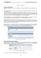
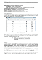
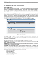
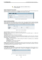
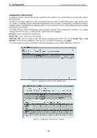
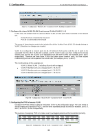
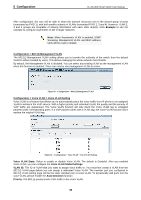
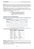
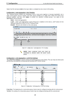
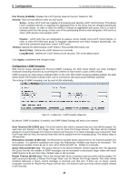
5 Configuration D-Link Web Smart Switch User Manual Figure 54 - Configuration > 802.1Q VLAN > Example VIDs Figure 55 - Configuration > 802.1Q VLAN > VID Assignments Configuration > Asymmetric VLAN This function is located in the 802.1Q Configuration page. It allows devices in different VLANs to communicate with the servers, firewalls or other shared resources in the shared VLAN. This configuration is accomplished in three steps: Enabling Asymmetric VLAN function Creating shared VLAN and access VLAN Configuring the PVID of access VLAN Asymmetric VLAN is especially effective when used in a small network where a L3 routing device is absent, or if the resource to be shared is not capable of supporting tagged VLAN (for example, a printer). The example below is a typical application of Asymmetric VLAN. Servers and firewall are located in shared VLAN (default VLAN), and PCs 1, 2 and 3 are located in different VLAN. Because VLANs remain separate, PCs 1, 2, and 3 cannot communicate with each other; but all of them need to access the servers or the Internet behind the firewall. PC 1 (Port 5, V2) PC 2 (Port 6, V3) PC 3 (Port 7, V4) Firewall, V1~V4 Servers, V1~V4 Figure 56 - Configuration > 802.1Q VLAN > Asymmetric VLAN Example 1. Enable Asymmetric VLAN Enable Asymmetric VLAN and click the Apply button. The overlapping VLAN cannot be configured unless this function is enabled.. 33
-
 1
1 -
2
-
3
-
4
-
5
-
6
-
7
-
8
-
9
-
10
-
11
-
12
-
13
-
14
-
15
-
16
-
17
-
18
-
19
-
20
-
21
-
22
-
23
-
24
-
25
-
26
-
27
-
28
-
29
-
30
-
31
-
 32
32 -
 33
33 -
 34
34 -
 35
35 -
 36
36 -
 37
37 -
 38
38 -
 39
39 -
 40
40 -
 41
41 -
 42
42 -
43
-
44
-
45
-
46
-
47
-
48
-
49
-
50
-
51
-
52
-
53
-
54
-
55
-
56
-
57
-
58
-
59
-
60
-
61
-
62
-
63
-
64
-
65
-
66
-
67
-
68
-
69
-
70
-
71
 |
 |
