D-Link DGS-1500-52 User Manual - Page 81
SNMP > RMON > RMON History
 |
View all D-Link DGS-1500-52 manuals
Add to My Manuals
Save this manual to your list of manuals |
Page 81 highlights
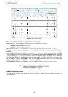
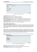
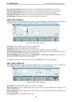
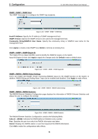
5 Configuration D-Link Web Smart Switch User Manual SNMP > RMON > RMON History The RMON History Control Configuration page contains information about samples of data taken from ports. For example, the samples may include interface definitions or polling periods. Figure 5.105 - SNMP > RMON > RMON History The History Control Configuration contains the following fields: Index (1 - 65535): Indicates the history control entry number. Port: Specifies the port from which the RMON information was taken. Buckets Requested (1 ~ 50): Specifies the number of buckets that the device saves. Interval (1 ~ 3600): Indicates in seconds the time period that samplings are taken from the ports. The field range is 1-3600. The default is 1800 seconds (equal to 30 minutes). Owner: Displays the RMON station or user that requested the RMON information. Click Add to make the configurations take effects. SNMP > RMON > RMON Alarm The RMON Alarm Configuration page allows the user to configure the network alarms. Network alarms occur when a network problem, or event, is detected. Figure 5.106 - SNMP > RMON > RMON Alarm The configuration contains the following fields: Index (1 - 65535): Indicates a specific alarm. Variable: Specify the selected MIB variable value. Rising Threshold (0 ~ 2^31-1): Displays the rising counter value that triggers the rising threshold alarm. Rising Event Index (1 ~ 65535): Displays the event that triggers the specific alarm. The possible field values are user defined RMON events. Owner: Displays the device or user that defined the alarm. Interval (1 ~ 2^31-1): Defines the alarm interval time in seconds. Sample type: Defines the sampling method for the selected variable and comparing the value against the thresholds. The possible field values are: Delta value - Subtracts the last sampled value from the current value. The difference in the values is compared to the threshold. Absolute value - Compares the values directly with the thresholds at the end of the sampling interval. Falling Threshold (0 ~ 2^31-1): Displays the falling counter value that triggers the falling threshold alarm. 75
-
 1
1 -
2
-
3
-
4
-
5
-
6
-
7
-
8
-
9
-
10
-
11
-
12
-
13
-
14
-
15
-
16
-
17
-
18
-
19
-
20
-
21
-
22
-
23
-
24
-
25
-
26
-
27
-
28
-
29
-
30
-
31
-
32
-
33
-
34
-
35
-
36
-
37
-
38
-
39
-
40
-
41
-
42
-
43
-
44
-
45
-
46
-
47
-
48
-
49
-
50
-
51
-
52
-
53
-
54
-
55
-
56
-
57
-
58
-
59
-
60
-
61
-
62
-
63
-
64
-
65
-
66
-
67
-
68
-
69
-
70
-
71
-
72
-
73
-
74
-
75
-
 76
76 -
 77
77 -
 78
78 -
 79
79 -
 80
80 -
 81
81 -
 82
82 -
 83
83 -
 84
84 -
 85
85 -
 86
86 -
87
-
88
-
89
-
90
-
91
-
92
-
93
-
94
-
95
-
96
-
97
 |
 |
