D-Link DGS-3120-48PC Hardware Installation Guide - Page 13
Front Panel Components, The front panel of the Switch consists of LED indicators for Power, Console - switch dgs 48tc
 |
View all D-Link DGS-3120-48PC manuals
Add to My Manuals
Save this manual to your list of manuals |
Page 13 highlights
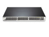
xStack® DGS-3120 Series Layer 2 Managed Stackable Gigabit Switch Hardware Installation Guide Front Panel Components The front panel of the Switch consists of LED indicators for Power, Console, RPS, Master, S1, S2, Fan, SD, Stack ID, and for Link/Act for each port on the Switch including SFP port LEDs. A separate table below describes LED indicators in more detail. The DGS-3120-24PC and DGS-3120-48PC switches are equipt with an additional PoE light, to indication whether the ports are running in Power over Ethernet mode. Figure 1- 1. Front panel view of the DGS-3120-24TC Figure 1- 2. Front panel view of the DGS-3120-24SC Figure 1- 3. Front panel view of the DGS-3120-24SC-DC Figure 1- 4. Front panel view of the DGS-3120-24PC Figure 1- 5. Front panel view of the DGS-3120-48TC Figure 1- 6. Front panel view of the DGS-3120-48PC 5
-
 1
1 -
2
-
3
-
4
-
5
-
6
-
7
-
 8
8 -
 9
9 -
 10
10 -
 11
11 -
 12
12 -
 13
13 -
 14
14 -
 15
15 -
 16
16 -
 17
17 -
 18
18 -
19
-
20
-
21
-
22
-
23
-
24
-
25
-
26
-
27
-
28
-
29
-
30
-
31
-
32
-
33
-
34
-
35
-
36
-
37
-
38
-
39
-
40
-
41
-
42
-
43
-
44
-
45
-
46
-
47
-
48
-
49
-
50
-
51
-
52
 |
 |
