D-Link DGS-3120-48PC Hardware Installation Guide - Page 16
Rear Panel Description, optional external Redundant Power Supply DPS-200 for DGS-3120-24TC/SC
 |
View all D-Link DGS-3120-48PC manuals
Add to My Manuals
Save this manual to your list of manuals |
Page 16 highlights
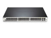
xStack® DGS-3120 Series Layer 2 Managed Stackable Gigabit Switch Hardware Installation Guide Rear Panel Description The rear panel contains an AC power connector, an outlet for an external redundant power supply, and two stacking ports. Figure 1- 13. Rear panel view of the DGS-3120-24TC Figure 1- 14. Rear panel view of the DGS-3120-24SC Figure 1- 15. Rear panel view of the DGS-3120-24SC-DC Figure 1- 16. Rear panel view of the DGS-3120-24PC Figure 1- 17. Rear panel view of the DGS-3120-48TC Figure 1- 18. Rear panel view of the DGS-3120-48PC The AC power connector is a standard three-pronged connector that supports the power cord. Plug-in the female connector of the provided power cord into this socket, and the male side of the cord into a power outlet. The Switch automatically adjusts the power setting to any supply voltage in the range from 100 ~ 240 VAC at 50 ~ 60 Hz. An optional external Redundant Power Supply (DPS-200 for DGS-3120-24TC/SC, DPS-500/DPS-500DC for DGS-312048TC, and DPS-700 for DGS-3120-24PC/48PC) can be plugged into the RPS outlet displayed above. When the internal power fails, this optional external RPS will take over all the power immediately and automatically. There are also two stacking ports on the rear panel. These dedicated stacking ports are specially designed for high speed switch stacking. The Switch supports a stacking cable length of up to 3 meters. 8
-
 1
1 -
2
-
3
-
4
-
5
-
6
-
7
-
8
-
9
-
10
-
 11
11 -
 12
12 -
 13
13 -
 14
14 -
 15
15 -
 16
16 -
 17
17 -
 18
18 -
 19
19 -
 20
20 -
 21
21 -
22
-
23
-
24
-
25
-
26
-
27
-
28
-
29
-
30
-
31
-
32
-
33
-
34
-
35
-
36
-
37
-
38
-
39
-
40
-
41
-
42
-
43
-
44
-
45
-
46
-
47
-
48
-
49
-
50
-
51
-
52
 |
 |
