D-Link DS-810 User Guide - Page 33
Connector Pinouts
 |
View all D-Link DS-810 manuals
Add to My Manuals
Save this manual to your list of manuals |
Page 33 highlights
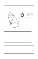
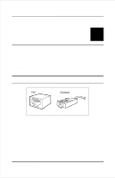
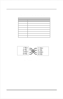
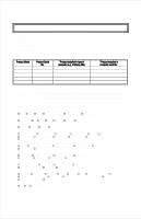
10/100 Fast Ethernet Switch User's Guide B 5 CONNECTOR PINOUTS This appendix describes the RJ-45 connector pinouts. RJ-45 Connectors Figure B-1 RJ-45 Connector The above figure shows the arrangements of the pins, while Table B-1 lists the pinouts. Connector Pinouts 23
-
 1
1 -
2
-
3
-
4
-
5
-
6
-
7
-
8
-
9
-
10
-
11
-
12
-
13
-
14
-
15
-
16
-
17
-
18
-
19
-
20
-
21
-
22
-
23
-
24
-
25
-
26
-
27
-
 28
28 -
 29
29 -
 30
30 -
 31
31 -
 32
32 -
 33
33 -
 34
34 -
 35
35 -
 36
36 -
 37
37 -
 38
38
 |
 |

10/100 Fast Ethernet Switch User’s Guide
Connector Pinouts
23
B
5
C
ONNECTOR
P
INOUTS
This appendix describes the RJ-45 connector pinouts.
RJ-45 Connectors
Figure B-1
RJ-45 Connector
The above figure shows the arrangements of the pins, while Table B-1 lists
the pinouts.