D-Link DSN-3200 Light Fix - Page 8
Installing the Resistor Packs - 10 power
 |
UPC - 790069299759
View all D-Link DSN-3200 manuals
Add to My Manuals
Save this manual to your list of manuals |
Page 8 highlights
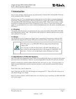
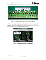
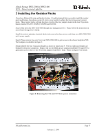
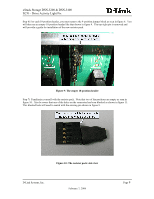
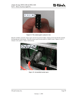
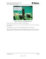
xStack Storage DSN-3200 & DSN-3400 ECN - Drive Activity Light Fix 2 Installing the Resistor Packs If you have followed the steps outlined in Section 1.3 and determined that you need to install the resistor pack modification, then please contact D-Link or your reseller to obtain the four (4) necessary resistor packs. These resistor packs will take the place of each of the four jumpers found on the four 10-position headers labeled NA1315, NA0912, NA0508 and NA0104. Step 1) Shut down the DSN-3200/3400 through your management GUI. Please follow the instructions in your xStack Storage User's Guide. Step 2) In order to minimize electrical shock risk, remove the three power cords from your DSN-3200/3400 unit's power supply. Step 3) Please remove the cover from your DSN-3200/3400 to gain access to the chassis backplane PCB. The backplane is identified in figure 3. Step 4) Identify the four 10-position headers as shown in figures 4 & 5. The two right-most headers are blocked by the power connectors. Remove the two (2) Molex power connectors labeled CN4 and CN7 to gain easier access to the two (2) 10-position jumpers found below them. Please see figure 8 for details. Figure 8: Removing the CN4 and CN7 Molex power connectors D-Link Systems, Inc. February 7, 2008 Page 8
-
 1
1 -
2
-
 3
3 -
 4
4 -
 5
5 -
 6
6 -
 7
7 -
 8
8 -
 9
9 -
 10
10 -
 11
11
 |
 |
