D-Link DWC-2000-AP32-LIC Quick Installation Guide - Page 2
About This Guide, Product Overview
 |
View all D-Link DWC-2000-AP32-LIC manuals
Add to My Manuals
Save this manual to your list of manuals |
Page 2 highlights
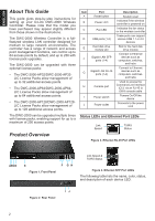
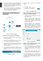
ENGLISH About This Guide This guide gives step-by-step instructions for setting up your D-Link DWC-2000 Wireless Controller. Please note that the model you have purchased may appear slightly different from those shown in the illustrations. The DWC-2000 Wireless Controller is a fullfeatured wireless LAN controller designed for medium to large network environments. The controller has a range of network and access point management functions, can control up to 64 access points by default, and up to 256 with license pack upgrades. The DWC-2000 can be upgraded with three optional license packs: • The DWC-2000-AP32/DWC-2000-AP32LIC License Packs allow management of up to 32 additional access points. • The DWC-2000-AP64/DWC-2000-AP64LIC License Packs allow management of up to 64 additional access points. • The DWC-2000-AP128/DWC-2000-AP128LIC License Packs allow management of up to 128 additional access points. The DWC-2000 can be upgraded multiple times with license packs, enabling support for up to a maximum of 256 access points. Product Overview Item A B C D E F G H I J Part Reset button Power LED Fan LED USB ports (1-2) Hard disk drive module slot Gigabit LAN SFP ports (1-4) Gigabit LAN RJ-45 ports (1-4) Console port Power switch Power outlet Description System reset Indicates if the wireless controller is powered on Indicates the fan status on the wireless controller These ports can support various USB 1.1 or 2.0 devices Slot for the hard disk drive module Connect to Ethernet devices such as computers, switches, and hubs Connect to Ethernet devices such as computers, switches, and hubs Used to access the Command Line Interface (CLI) via an RJ-45 to DB-9 console cable Powers On/Off the device Connects to the power cord Status LEDs and Ethernet Port LEDs Link Speed TX/RX Status Figure 3. Ethernet RJ-45 Port LEDs ABCD E Figure 1. Front Panel F GH Link Speed & TX/RX Status Figure 4. Ethernet SFP Port LEDs The following table lists the name, color, status, and description of each device LED. IJ Figure 2. Rear Panel 2
-
 1
1 -
 2
2 -
 3
3 -
 4
4 -
 5
5 -
 6
6 -
 7
7 -
 8
8
 |
 |
