D-Link DWL-8600AP Administration Guide - Page 107
Onfiguring, Iewing, Hannel, Anagement, Ettings
 |
View all D-Link DWL-8600AP manuals
Add to My Manuals
Save this manual to your list of manuals |
Page 107 highlights
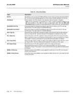
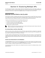
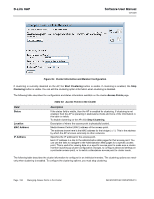
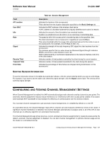
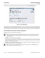
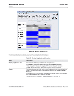
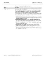
Software User Manual 12/10/09 D-Link UAP Field AP Location User MAC Idle Rate Signal Receive Total Transmit Total Error Rate Table 46: Session Management Description Indicates the location of the access point. This is derived from the location description specified on the Basic Settings tab. Indicates the MAC address of the wireless client device. A MAC address is a hardware address that uniquely identifies each node of a network. Indicates the amount of time this station has remained inactive. A station is considered to be idle when it is not receiving or transmitting data. The speed at which this access point is transferring data to the specified client. The data transmission rate is measured in megabits per second (Mbps). This value should fall within the range of the advertised rate set for the mode in use on the access point. For example, 6 to 54 Mbps for 802.11a. Indicates the strength of the radio frequency (RF) signal the client receives from the access point. The measure used for this is a value known as Received Signal Strength Indication (RSSI), and will be a value between 0 and 100. RSSI is determined by a mechanism implemented on the network interface card (NIC) of the client station. Indicates number of total packets received by the client during the current session. Indicates number of total packets transmitted to the client during this session. Indicates the percentage of time frames are dropped during transmission on this access point. SORTING SESSION INFORMATION To sort the information shown in the tables by a particular indicator, click the column label by which you want to order things. For example, if you want to see the table rows ordered by signal strength, click the Signal column label. The entries will be sorted by signal strength. CONFIGURING AND VIEWING CHANNEL MANAGEMENT SETTINGS When Channel Management is enabled, the UAP automatically assigns radio channels used by clustered access points. The automatic channel assignment reduces mutual interference (or interference with other access points outside of its cluster) and maximizes Wi-Fi bandwidth to help maintain the efficiency of communication over the wireless network. You must start channel management to get automatic channel assignments; it is disabled by default on a new AP. At a specified interval, the Channel Manager maps APs to channel use and measures interference levels in the cluster. If significant channel interference is detected, the Channel Manager automatically re-assigns some or all of the APs to new channels per an efficiency algorithm (or automated channel plan). The Channel Management page shows previous, current, and planned channel assignments for clustered access points. By default, automatic channel assignment is disabled. You can start channel management to optimize channel usage across the cluster on a scheduled interval. 34CSFP6XXUAP-SWUM100-D13 Configuring and Viewing Channel Management Settings Page 107
-
 1
1 -
2
-
3
-
4
-
5
-
6
-
7
-
8
-
9
-
10
-
11
-
12
-
13
-
14
-
15
-
16
-
17
-
18
-
19
-
20
-
21
-
22
-
23
-
24
-
25
-
26
-
27
-
28
-
29
-
30
-
31
-
32
-
33
-
34
-
35
-
36
-
37
-
38
-
39
-
40
-
41
-
42
-
43
-
44
-
45
-
46
-
47
-
48
-
49
-
50
-
51
-
52
-
53
-
54
-
55
-
56
-
57
-
58
-
59
-
60
-
61
-
62
-
63
-
64
-
65
-
66
-
67
-
68
-
69
-
70
-
71
-
72
-
73
-
74
-
75
-
76
-
77
-
78
-
79
-
80
-
81
-
82
-
83
-
84
-
85
-
86
-
87
-
88
-
89
-
90
-
91
-
92
-
93
-
94
-
95
-
96
-
97
-
98
-
99
-
100
-
101
-
 102
102 -
 103
103 -
 104
104 -
 105
105 -
 106
106 -
 107
107 -
 108
108 -
 109
109 -
 110
110 -
 111
111 -
 112
112 -
113
-
114
-
115
-
116
-
117
-
118
-
119
-
120
-
121
-
122
-
123
-
124
-
125
-
126
-
127
-
128
-
129
-
130
-
131
-
132
-
133
-
134
-
135
 |
 |
