Dacor ER36G Installation Instructions - Page 10
Adjust the Range Height, Self-Rimming Trim Installation cont.
 |
View all Dacor ER36G manuals
Add to My Manuals
Save this manual to your list of manuals |
Page 10 highlights
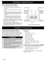
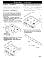
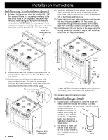
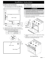
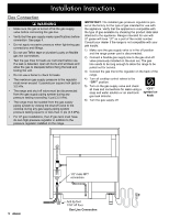
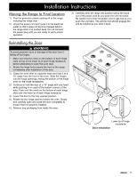
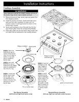
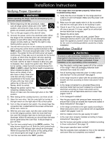
Installation Instructions Self-Rimming Trim Installation (cont.) 8) Re-attach the backguard using the supplied #8 x 1/4" Torx screws. If there is a countertop overhang to the rear of the range of 3/4" or greater, attach the rear trim piece to the backguard as shown below during re-installation. IMPORTANT: To ensure proper fit, do not use the screws removed from the range in previous steps. Use only the provided #8 x 1/4" Torx screws. Rear trim piece (optional) 11) Attach the self-rimming side panels included with the unit by snapping the ball studs on the front into the back of the control panel and kick panel. The finished side of each side panel faces out. 12) Fasten the top of each side panel to the control panel with two of the included #8 x 1/4" Torx screws (A). Insert them through the holes created when the end caps were removed in step 10 and tighten into place. 13) Finish fastening the side panels to the range using the existing screws (B) removed in step 9. Two screws will be left over and may be discarded. B A B Control panel 9) Remove and retain the screws (4 each side) from the factory installed side panels on the unit. Remove the side panels. 10) Remove both control panel end cap screws and remove both end caps. The end cap screws are accessed through holes on the under side of the trim protruding from the front of the control panel. Remove end cap, both sides Remove both side panels 8 A B B Ball studs Kick panel B B A) #8 x 1/4" Torx screw included with range (2 places) B) Existing screw removed in step 9 (6 places) 14) Replace the control panel end caps. Adjust the Range Height 1) For stand alone configurations, raise the range until the top of the trim around the cooktop is at least the same height as the countertop. For self-rimming configurations, raise the range until the bottom of the trim surrounding the cooktop is even with the countertop. To adjust the height, turn the foot on the bottom of each leg as shown below. 2) Use a level to make sure that the range does not up tilt front to back or side to side. Readjust the legs as necessary. down
-
 1
1 -
2
-
3
-
4
-
 5
5 -
 6
6 -
 7
7 -
 8
8 -
 9
9 -
 10
10 -
 11
11 -
 12
12 -
 13
13 -
 14
14 -
 15
15 -
16
-
17
-
18
-
19
-
20
 |
 |
