Dacor ERV48 Installation Instructions - Page 8
Planning the Duct Work - model
 |
View all Dacor ERV48 manuals
Add to My Manuals
Save this manual to your list of manuals |
Page 8 highlights
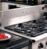
Installation Specifications Planning the Duct Work warning • To reduce the risk of fire and to properly exhaust air, be sure to duct air outside the house or building. Do not vent exhaust air into spaces within walls or ceilings or into attics, crawl spaces or garages. • Tape all duct joints securely to prevent combustion by-products, smoke or odors from entering the home. Doing so will also improve system efficiency. • TO REDUCE THE RISK OF FIRE, USE ONLY METAL DUCT WORK. • DO NOT install more than one blower to increase the length of the duct run. Even small differences between blower air flow rates can greatly reduce the air draw by the raised vent. You must install one of the Dacor remote or in-line blower models listed below for the raised vent to operate properly. See the blower installation instructions for directions. Only one blower shall be installed. APPROVED DACOR BLOWERS FOR USE WITH MODEL ERV AND PRV SERIES RAISED VENTS Model Number REMP3 REMP16 ILHSF8 ILHSF10 Rating* 600 CFM 1000 CFM 600 CFM 1100 CFM • When connecting the duct work to the back of the unit, the customer must supply a 3 ¼" X 10" rectangular transition to make the connection. • For side and bottom exhaust connections, use the supplied ATD2 transition to connect the duct work to the unit. It transitions between the 1 5/8" X 16" exhaust outlet on the unit and a 3 ¼" X 10" rectangular duct connection. On bottom exhaust installations cut a hole in the floor to allow the transition and/or duct work to pass through the floor (see page 8). * Nominal rating at zero inches static pressure. See blower installation instructions for actual ratings. The raised vent can be configured to exhaust through the back, the bottom or either side by removing the appropriate exhaust knock out shown below. 5" (12.7 cm) 2" X 16", connects to side or bottom exhaust on raised vent 26" (66.0 cm) 1 1/8" (2.9 cm) 6 1/4" CL (15.9 cm) Front of unit 1" (2.5 cm) 3 ¼" X 10" to duct work Motor ADT2 Transition cover CL • All duct work materials (including screws and duct tape) must be purchased separately by the customer. • When planning new duct work, always look for the shortest, most direct route to the outside. See page 3" CL 5 for examples. • You can increase the duct size over the duct run if desired. To prevent a back draft, never decrease the Rear Exhaust Knock Out (3 ¼" X 10") duct size over the run. Vertical center line of rear exhaust knock out lines up with vertical center line of chassis Bottom Exhaust Knock Out (1 5/8" X 16") On 46" and 48" wide models, the vertical center line of bottom knock- • Do not rely on duct tape alone to seal duct joints. Fasten all connections with sheet metal screws and tape all joints with certified silver tape or duct tape. out lines up with vertical center line of chassis • Use sheet metal screws as required to support the duct On 30" and 36" wide models, the vertical center line of bottom knock- out is offset 3" weight. Side Exhaust Knock Outs (1 5/8" X 16") • To prevent back-drafts, a damper at the duct outlet may also be required. 6
-
 1
1 -
2
-
 3
3 -
 4
4 -
 5
5 -
 6
6 -
 7
7 -
 8
8 -
 9
9 -
 10
10 -
 11
11 -
 12
12 -
 13
13 -
14
-
15
-
16
 |
 |
