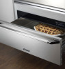
Dacor EWD24 Installation Instructions - Page 5
Installation Specifications - iwd24 warming drawer
 |
View all Dacor EWD24 manuals
Add to My Manuals
Save this manual to your list of manuals |
Page 5 highlights
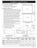
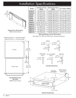
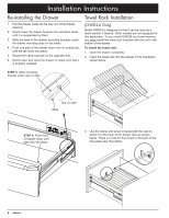
Installation Specifications Verifying the Package Contents • (3) mounting screws - PN 83569 • Wire rack with mounting hardware (OWD24 only) (1) PN 83619 (screw), (1) PN 83267 (clamp) Installation Planning • A qualified technician must complete the installation of this builtin appliance. Proper installation is the customer's responsibility. • Carefully check the location where the drawer is to be installed. The drawer should be placed for convenient access. Make certain that electrical power can be provided in the selected location. Install the warming drawer in wood cabinets only. • Plan the installation so that all minimum clearances are met or exceeded. Dimensions shown provide minimum clearances, unless otherwise noted. Be certain that proper clearance is provided for the drawer door when it is in the open position. • The specified minimum cabinet depth and width must be provided. The cabinet depth and width must completely enclose the recessed portion of the drawer. • Cabinet cutout dimensions must be used as indicated. All contact surfaces between the appliance and the cabinet must be solid and level. The drawer support platform must be flush with the bottom edge of the cabinet cutout. • Make certain that you have everything necessary to ensure a proper installation before proceeding. • A custom front panel is required for IWD series models and optional for OWD24. • An optional Epicure® style front panel kit is available for model OWD24. ** ** C B Chassis E 5/16" (8 mm) Drawer open F Overall Dimensions - IWD/OWD Series Top View Mounting hole, 9 places 40" (101.6 cm) 3 prong 120 Vac power cord ** ** G D Chassis without drawer installed A ** = OWD24 mounting holes Drawer Face Dimensions (IWD/OWD Series) Chassis Dimensions (IWD/OWD Series) Model IWD24 IWD27 IWD30 OWD24 (A) Dimension Drawer Face Width (B) Dimension Chassis Width (C) Dimension Chassis Face Width (D) Dimension Drawer Face Height (E) Dimension Chassis Depth (F) Dimension Drawer Depth (G) Dimension Chassis Height 22 5/16" (56.7 cm) 22 1/4" (56.5 cm) 22 3/8" (56.8 cm) 25 5/16" (64.3 cm) 25 1/4" (64.1 cm) 25 3/8" (64.5 cm) 28 5/16" (71.9 cm) 28 1/4" (71.8 cm) 28 3/8" (72.1 cm) 8 15/16" (22.7 cm) 23 3/8" (59.4 cm) 23 13/16" (60.5 cm) 9 1/16" (23.0 cm) 22 1/2" (57.1 cm) 22 1/2" (57.1 cm) 22 1/2" (57.1 cm) 11 7/8" (30.2 cm) 20" (50.8 cm) 18" (45.7 cm) 11 7/8" (30.2 cm) See following page for chassis dimensions for other models 3
-
 1
1 -
 2
2 -
 3
3 -
 4
4 -
 5
5 -
 6
6 -
 7
7 -
 8
8 -
 9
9 -
 10
10 -
 11
11 -
12
 |
 |
