Danby DPAC12012P Product Manual - Page 5
ki>
 |
View all Danby DPAC12012P manuals
Add to My Manuals
Save this manual to your list of manuals |
Page 5 highlights
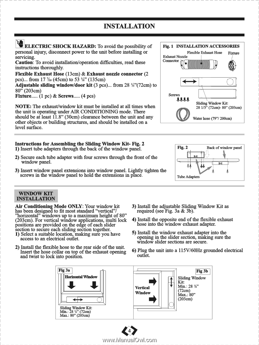
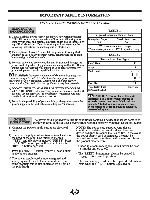
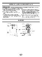
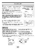
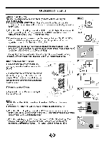
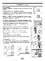
INSTALLATION ELECTRIC SHOCK HAZARD: To avoid the possibility of personal injury, disconnect power to the unit before installing or servicing. Caution: To avoid installation/operation difficulties, read these instructions thoroughly. Flexible Exhaust Hose (13cm) & Exhaust nozzle connector (2 pcs)... from 17'/o (45cm) to 53 1/6" (135cm) Adjustable sliding window/door kit (3 pcs)... from 28 '/3"(72cm) to 80" (203cm) Fixture (1 pc) & Screws (4 pcs) NOTE: The exhaust/window kit must be installed at all times when the unit is operating under AIR CONDITIONING mode. There should be at least 11.8" (30cm) clearance between the unit and any other objects or building structures, and should be installed on a level surface. Fig. 1 INSTALLATION ACCESSORIES Flexible Exhaust Hose Fixture Exhaust Nozzle Connector Screws 4444 Sliding Window Kit: 28 1/3" (72cm)- 80" (203cm) (t) Water hose (79"/ 200cm) Instructions for Assembling the Sliding Window Kit- Fig. 2 1) Insert tube adapters through the back of the window panel. 2) Secure each tube adapter with four screws through the front of the window panel. 3) Insert window panel extensions into window panel. Lightly tighten the screws in the window panel to hold the extensions in place. Fig. 2 Back of window panel 44 4$ Thbe Adapters WINDOW KIT INSTALLATION Air Conditioning Mode ONLY: Your window kit has been designed to fit most standard "vertical"! "horizontal" windows up to a maximum height of 80" (203cm). For vertical window applications, multi lock positions are provided on the edge of each slider section to secure each sliding section together. 1) Select a suitable location, making sure you have access to an electrical outlet. 2) Install the flexible hose to the rear side of the unit. Insert the hose collar on top of the exhaust opening and twist to lock into position. 3) Install the adjustable Sliding Window Kit as required (see Fig. 3a & 3b). 4) Install the opposite end of the flexible exhaust hose into the window exhaust adapter. 5) Install the window exhaust adapter into the opening in the slider section, making sure the window slider sections are secure. 6) Plug the unit into a 115V/60Hz grounded electrical outlet. Fig 3a Horizontal Window O Sliding Window Kit: Min.: 28 '/3" (72cm) Max.: 80" (203cm) Vertical Window 4 ki> Fig 3b Sliding Window Kit: Min.: 28 'A" (72cm) Max.: 80" (203cm)
-
 1
1 -
 2
2 -
 3
3 -
 4
4 -
 5
5 -
 6
6 -
 7
7 -
 8
8 -
 9
9 -
 10
10 -
 11
11 -
12
-
13
 |
 |