Danby DPAC12012P Product Manual - Page 8
OPERATION, cont'd
 |
View all Danby DPAC12012P manuals
Add to My Manuals
Save this manual to your list of manuals |
Page 8 highlights
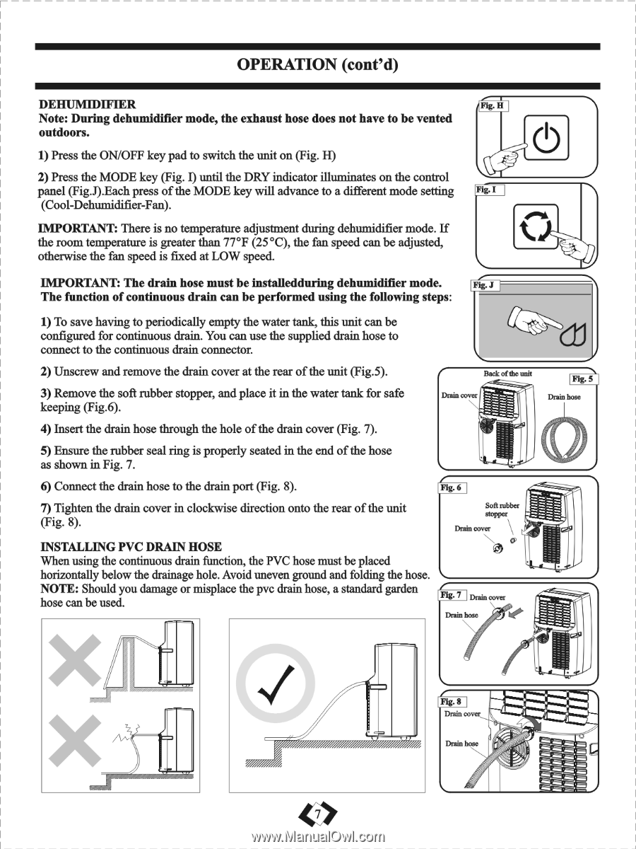
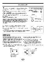
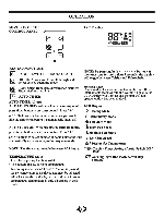
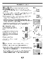
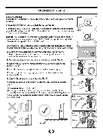
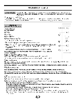
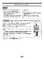
OPERATION (cont'd) DEHUMIDIFIER Fig. H Note: During dehumidifier mode, the exhaust hose does not have to be vented outdoors. 1) Press the ON/OFF key pad to switch the unit on (Fig. H) 2) Press the MODE key (Fig. I) until the DRY indicator illuminates on the control panel (Fig.J).Each press of the MODE key will advance to a different mode setting .I (Cool-Dehumidifier-Fan). IMPORTANT: There is no temperature adjustment during dehumidifier mode. If the room temperature is greater than 77°F (25°C), the fan speed can be adjusted, otherwise the fan speed is fixed at LOW speed. IMPORTANT: The drain hose must be installedduring dehumidifier mode. .J The function of continuous drain can be performed using the following steps: 1) To save having to periodically empty the water tank, this unit can be configured for continuous drain. You can use the supplied drain hose to connect to the continuous drain connector. 2) Unscrew and remove the drain cover at the rear of the unit (Fig.5). Back of the unit 3) Remove the soft rubber stopper, and place it in the water tank for safe keeping (Fig.6). Drain cover 4) Insert the drain hose through the hole of the drain cover (Fig. 7). 5) Ensure the rubber seal ring is properly seated in the end of the hose as shown in Fig. 7. 6) Connect the drain hose to the drain port (Fig. 8). Fig. 6 7) Tighten the drain cover in clockwise direction onto the rear of the unit (Fig. 8). Soft rubber stoPPer Drain cover INSTALLING PVC DRAIN HOSE When using the continuous drain function, the PVC hose must be placed horizontally below the drainage hole. Avoid uneven ground and folding the hose. NOTE: Should you damage or misplace the pvc drain hose, a standard garden hose can be used. Fig- 7 Drain cover Drain hose lag. 5 Drain hose zz 7-7 Z7 4 Ft& 8 Drain cover imiCimmiZ a r4 1, Drain hose
-
 1
1 -
2
-
 3
3 -
 4
4 -
 5
5 -
 6
6 -
 7
7 -
 8
8 -
 9
9 -
 10
10 -
 11
11 -
 12
12 -
 13
13
 |
 |