Dell 964 All In One Photo Printer User's Guide2 - Page 7
Initial Setup Menu - professional photo printers
 |
View all Dell 964 All In One Photo Printer manuals
Add to My Manuals
Save this manual to your list of manuals |
Page 7 highlights
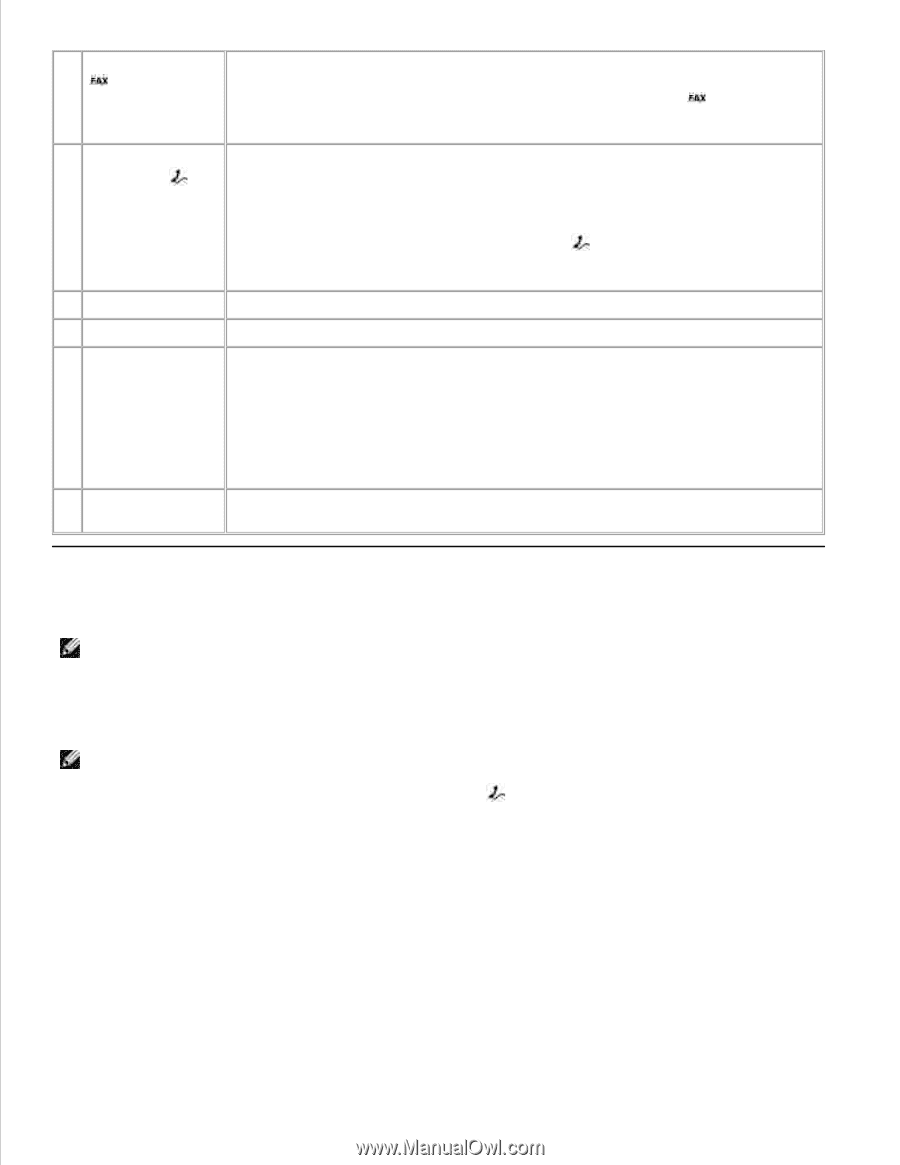
12 FAX connector ( -left side connector) 13 PHONE jack connector ( right side connector) 14 USB connector 15 Rear access door 16 Power supply Connects your printer to an active telephone line to send and receive faxes. NOTE: Do not connect additional devices to the FAX connector ( - left side connector) and do not connect a DSL (digital subscriber line) or ISDN (integrated services digital network) without using a digital line filter to the printer. Remove the blue plug to connect additional devices, such as a data/fax modem, telephone, or answering machine to your printer. NOTE: If the phone communication is serial in your country (such as Germany, Sweden, Denmark, Austria, Belgium, Italy, France, and Switzerland), you must remove the blue plug from the right connector ( ), and insert the supplied yellow terminator for your fax to work correctly. You will not be able to use this port for additional devices in these countries. Connects your printer to a computer. Open to remove paper jams. Supplies power to the printer. NOTE: The power supply is removable. When the power supply is removed from the printer, but remains plugged into a wall outlet, an LED is illuminated to notify you that power is present. 17 Power cord connector NOTE: If the power is off when you unplug your machine, the power will be off when you plug it back in. Connects printer power supply to power outlet using the supplied country-specific power cord. Setting Up Your Printer NOTE: The Dell Photo All-In-One Printer 964 supports Microsoft® Windows® 2000, Windows XP, and Windows XP Professional X64 Edition. To set up your printer, follow the steps on your Setting Up Your Printer poster. If you encounter problems during setup, see Troubleshooting . NOTE: The Dell Photo AIO Printer 964 is an analog device that only works when directly connected to a wall jack. Other devices such as a telephone or answering machine can be attached to the PHONE jack connector ( - right side connector) to pass through the printer as described in the setup steps. If you have a digital connection such as ISDN, DSL, or ADSL, a digital line filter is required. Contact your Internet Service Provider for details. Initial Setup Menu The printer automatically displays the Initial Setup menu when you power on the printer for the first time.
-
 1
1 -
 2
2 -
 3
3 -
 4
4 -
 5
5 -
 6
6 -
 7
7 -
 8
8 -
 9
9 -
 10
10 -
 11
11 -
 12
12 -
13
-
14
-
15
-
16
-
17
-
18
-
19
-
20
-
21
-
22
-
23
-
24
-
25
-
26
-
27
-
28
-
29
-
30
-
31
-
32
-
33
-
34
-
35
-
36
-
37
-
38
-
39
-
40
-
41
-
42
-
43
-
44
-
45
-
46
-
47
-
48
-
49
-
50
-
51
-
52
-
53
-
54
-
55
-
56
-
57
-
58
-
59
-
60
-
61
-
62
-
63
-
64
-
65
-
66
-
67
-
68
-
69
-
70
-
71
-
72
-
73
-
74
-
75
-
76
-
77
-
78
-
79
-
80
-
81
-
82
-
83
-
84
-
85
-
86
-
87
-
88
-
89
-
90
-
91
-
92
-
93
-
94
-
95
-
96
-
97
-
98
-
99
-
100
-
101
-
102
-
103
-
104
-
105
-
106
-
107
-
108
-
109
-
110
-
111
-
112
-
113
-
114
-
115
-
116
-
117
-
118
-
119
-
120
-
121
-
122
-
123
-
124
-
125
-
126
-
127
-
128
 |
 |