Dell Alienware M15x Service Manual - Page 104
Replacing the System Board
 |
UPC - 074450000064
View all Dell Alienware M15x manuals
Add to My Manuals
Save this manual to your list of manuals |
Page 104 highlights
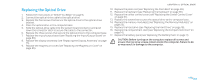
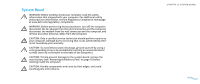
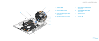
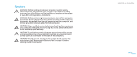
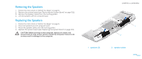
Replacing the System Board 1. Follow the instructions in "Before You Begin" on page 6. 2. Align the connectors on the system board with the slots on the computer. 3. Replace the five screws that secure the system board to the computer base. 4. Connect the following cables to their respective system board connectors: • audio cable • optical-drive cable • speaker cable • left- and right-speaker light cable • consumer IR board cable 5. Replace the graphics card (see "Replacing the Graphics Card" on page 70). 6. Replace the graphics card heat sink (see "Replacing the Graphics Card Heat Sink" on page 66). 7. Replace the graphics card fan (see "Replacing the Graphics Card Fan" on page 62). 8. Replace the processor (see "Replacing the Processor" on page 58). 9. Replace the processor fan and heat sink assembly (see "Replacing the Processor Fan and Heat Sink Assembly" on page 54). 10. Replace the full Mini-Card (see "Replacing the Full Mini-Card" on page 49). 11. Replace the half Mini-Card (see "Replacing the Half Mini-Card" on page 47). 12. Replace the display assembly (see "Replacing the Display Assembly" on page 75). 13. Replace the magnesium cover (see "Replacing the Magnesium Cover" on page 85). CHAPTER 22: SYSTEM BOARD 14. Replace the air vents (see "Replacing the Air Vents" on page 43). 15. Replace the keyboard (see "Replacing the Keyboard" on page 35). 16. Replace the center control cover (see "Replacing the Center Control Cover" on page 31). 17. Replace the palm rest (see "Replacing the Palm Rest" on page 39). 18. Replace the memory module(s) (see "Replacing the Memory Module(s)" on page 23). 19. Connect the coin-cell battery cable to the system board connector (see "Replacing the Coin-Cell Battery" on page 27). 20. Replace the hard drive (see "Replacing the Hard Drive" on page 18). 21. Replace the compartment door (see "Replacing the Compartment Door" on page 14). 22. Replace the battery pack (see "Replacing the Battery Pack" on page 11). CAUTION: Before turning on the computer, replace all screws and ensure that no stray screws remain inside the computer. Failure to do so may result in damage to the computer. 23. Turn on the computer. NOTE: After you have replaced the system board, enter the computer Service Tag into the BIOS of the replacement system board. 24. Enter the computer Service Tag in the Set Service Tag field of the System Setup. For more information, see "System Setup Options" on page 113. 0104 /0104
-
 1
1 -
2
-
3
-
4
-
5
-
6
-
7
-
8
-
9
-
10
-
11
-
12
-
13
-
14
-
15
-
16
-
17
-
18
-
19
-
20
-
21
-
22
-
23
-
24
-
25
-
26
-
27
-
28
-
29
-
30
-
31
-
32
-
33
-
34
-
35
-
36
-
37
-
38
-
39
-
40
-
41
-
42
-
43
-
44
-
45
-
46
-
47
-
48
-
49
-
50
-
51
-
52
-
53
-
54
-
55
-
56
-
57
-
58
-
59
-
60
-
61
-
62
-
63
-
64
-
65
-
66
-
67
-
68
-
69
-
70
-
71
-
72
-
73
-
74
-
75
-
76
-
77
-
78
-
79
-
80
-
81
-
82
-
83
-
84
-
85
-
86
-
87
-
88
-
89
-
90
-
91
-
92
-
93
-
94
-
95
-
96
-
97
-
98
-
 99
99 -
 100
100 -
 101
101 -
 102
102 -
 103
103 -
 104
104 -
 105
105 -
 106
106 -
 107
107 -
 108
108 -
 109
109 -
110
-
111
-
112
-
113
-
114
-
115
-
116
-
117
-
118
 |
 |
