Dell Alienware M17X R3 Service Manual (English Only) - Page 94
Replacing the Optical Drive
 |
View all Dell Alienware M17X R3 manuals
Add to My Manuals
Save this manual to your list of manuals |
Page 94 highlights
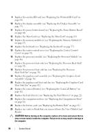
Replacing the Optical Drive 1 Follow the instructions in "Before You Begin" on page 9. 2 Replace the interposer to the optical drive. 3 Align the screw holes on the optical-drive bracket with the screw holes on the optical drive and replace the five screws. 4 Align the slot on the optical-drive bracket with the alignment posts on computer chassis and secure the optical-drive assembly in place. 5 Replace the two screws that secure the optical-drive assembly to the computer base. 6 Slide the optical drive cable into the connector on the system board and press down on the connector latch to secure the cable. 7 Replace the speakers (see "Replacing the Speakers" on page 88). 8 Replace the palm rest assembly (see "Replacing the Palm Rest Assembly" on page 81). 9 Replace the status light board (see "Replacing the Status Light Board" on page 76). 10 Replace the display assembly (see "Replacing the Display Assembly" on page 73). 11 Replace the power button board (see "Replacing the Power Button Board" on page 68). 12 Replace the keyboard (see "Replacing the Keyboard" on page 57). 13 Replace the center control cover (see "Replacing the Center Control Cover" on page 52). 14 Replace the compartment door (see "Replacing the Compartment Door" on page 16). 15 Replace the battery pack (see "Replacing the Battery Pack" on page 14). CAUTION: Before turning on the computer, replace all screws and ensure that no stray screws remain inside the computer. Failure to do so may result in damage to the computer. 94 Optical Drive
-
 1
1 -
2
-
3
-
4
-
5
-
6
-
7
-
8
-
9
-
10
-
11
-
12
-
13
-
14
-
15
-
16
-
17
-
18
-
19
-
20
-
21
-
22
-
23
-
24
-
25
-
26
-
27
-
28
-
29
-
30
-
31
-
32
-
33
-
34
-
35
-
36
-
37
-
38
-
39
-
40
-
41
-
42
-
43
-
44
-
45
-
46
-
47
-
48
-
49
-
50
-
51
-
52
-
53
-
54
-
55
-
56
-
57
-
58
-
59
-
60
-
61
-
62
-
63
-
64
-
65
-
66
-
67
-
68
-
69
-
70
-
71
-
72
-
73
-
74
-
75
-
76
-
77
-
78
-
79
-
80
-
81
-
82
-
83
-
84
-
85
-
86
-
87
-
88
-
 89
89 -
 90
90 -
 91
91 -
 92
92 -
 93
93 -
 94
94 -
 95
95 -
 96
96 -
 97
97 -
 98
98 -
 99
99 -
100
-
101
-
102
-
103
-
104
-
105
-
106
-
107
-
108
-
109
-
110
 |
 |
